Waveguide Routing
Single-port to Single-port
test
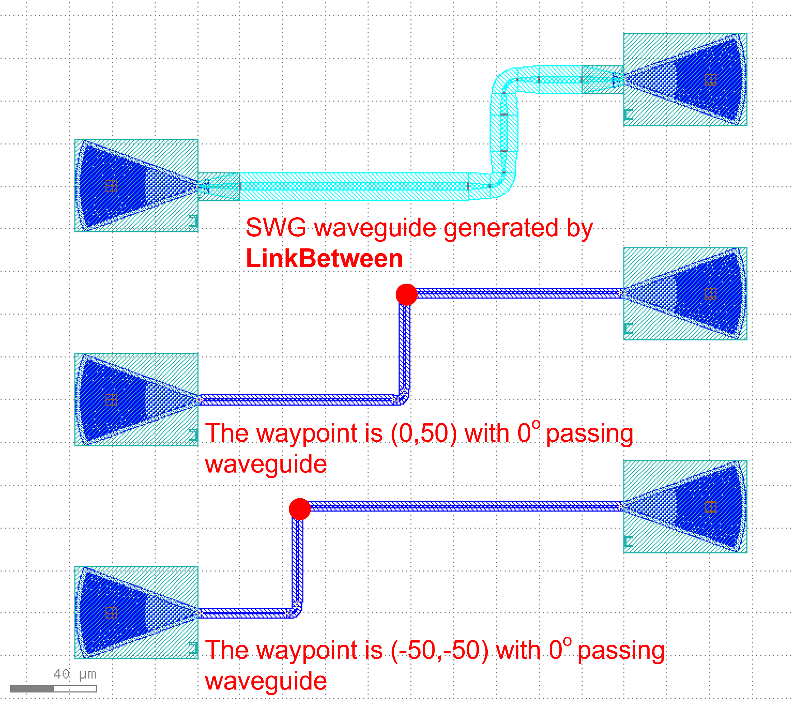
There are a total of three types of connections from single port to single port:
fp.LinkBetweenTECH.LINKER>>
Here’s a comparison of the three options
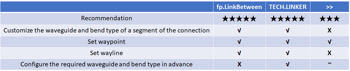
Among them, LinkBetween is relatively flexible and LINKER is relatively short and neat.
Examples
# Interconnecting device ports by calling fp.create_links
device = fp.create_links(
    link_type=TECH.WG.FWG.C.EXPANDED, # Define the type of straight waveguide in automatic routing
    bend_factory=TECH.WG.FWG.C.WIRE.BEND_CIRCULAR, # Define the type of bend during automatic routing
    # Define the connection relationship between device ports in specs
    specs=[
        gc1["op_0"] >> fp.Waypoint(-50, -50, 0) >> gc4["op_0"],  # Use >> to define connection relationships
        # Use LINKER to define the interconnection of the specified device port
        TECH.LINKER.SWG_WIRE_FWG_EULER(
            start=gc2["op_0"],
            end=gc5["op_0"],
            waypoints=[fp.Waypoint(0, 50, 0)]
        ),
        # Use LinkBetween to define a separate segment of the connection, and you can modify the type of the straight waveguide and bend with parameters.
        fp.LinkBetween(
            start=gc3["op_0"],
            end=gc6["op_0"],
            link_type=TECH.WG.SWG.C.EXPANDED,
            bend_factory=TECH.WG.SWG.C.WIRE.BEND_CIRCULAR,
            waypoints=[fp.Waypoint(50, 150, 0)]
        ),
    ],
)

insts += device  # Add the devices returned by Linked to insts
The differences between the two methods are:
LinkBetweenrequires setting thewaveguide_typeandbendfactoryto define the waveguide and bend in the routing.LINKERis already configured in thetechnologyfile, no need to definewaveguide_typeandbendfactoryagain.
Multi-port to Multi-port
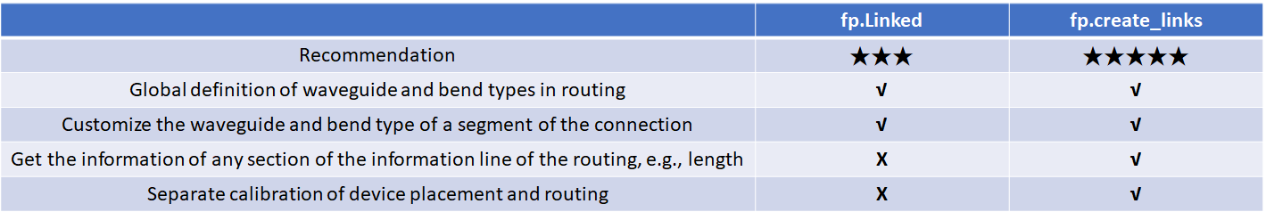
There are two types of connections from multi-port to multi-port.
fp.Linkedfp.create_links
Here’s a comparison of the two options
fp.Linked example ( Recommendation★★★ )
# Call the device
GC = pdk.GratingCoupler(waveguide_type=TECH.WG.FWG.C.WIRE,teeth=25)

# Place the device in different locations
gc1 = GC.h_mirrored().translated(-100, -100)
gc2 = GC.h_mirrored().translated(-100, 0)
gc3 = GC.h_mirrored().translated(-100, 100)
gc4 = GC.translated(100, -50)
gc5 = GC.translated(100, 50)
gc6 = GC.translated(100, 150)

# Interconnecting device ports by calling the Linked method
device = fp.Linked(
    link_type=TECH.WG.FWG.C.EXPANDED,  # Define the type of straight waveguide in automatic routing
    bend_factory=TECH.WG.FWG.C.WIRE.BEND_CIRCULAR,  # Define the type of bend in automatic routing
    # Define the connection between device ports in links
    links=[
        gc1["op_0"] >> fp.Waypoint(-50, -50, 0) >> gc4["op_0"],  # Use >> to define connections between two ports
        gc2["op_0"] >> fp.Waypoint(0, 50, 0) >> gc5["op_0"],  # Use fp.Waypoint(x,y) to define the path point
        # Use LinkBetween to define a separate segment of the connection,
        # and you can modify the type of the straight waveguide and bend with parameters
        fp.LinkBetween(
            start=gc3["op_0"],
            end=gc6["op_0"],
            link_type=TECH.WG.SWG.C.EXPANDED,
            bend_factory=TECH.WG.SWG.C.WIRE.BEND_CIRCULAR,
            waypoints=[fp.Waypoint(50, 150, 0)]
        )
    ],
    ports=[],
)

insts += device  # Add the device returned by Linked to insts
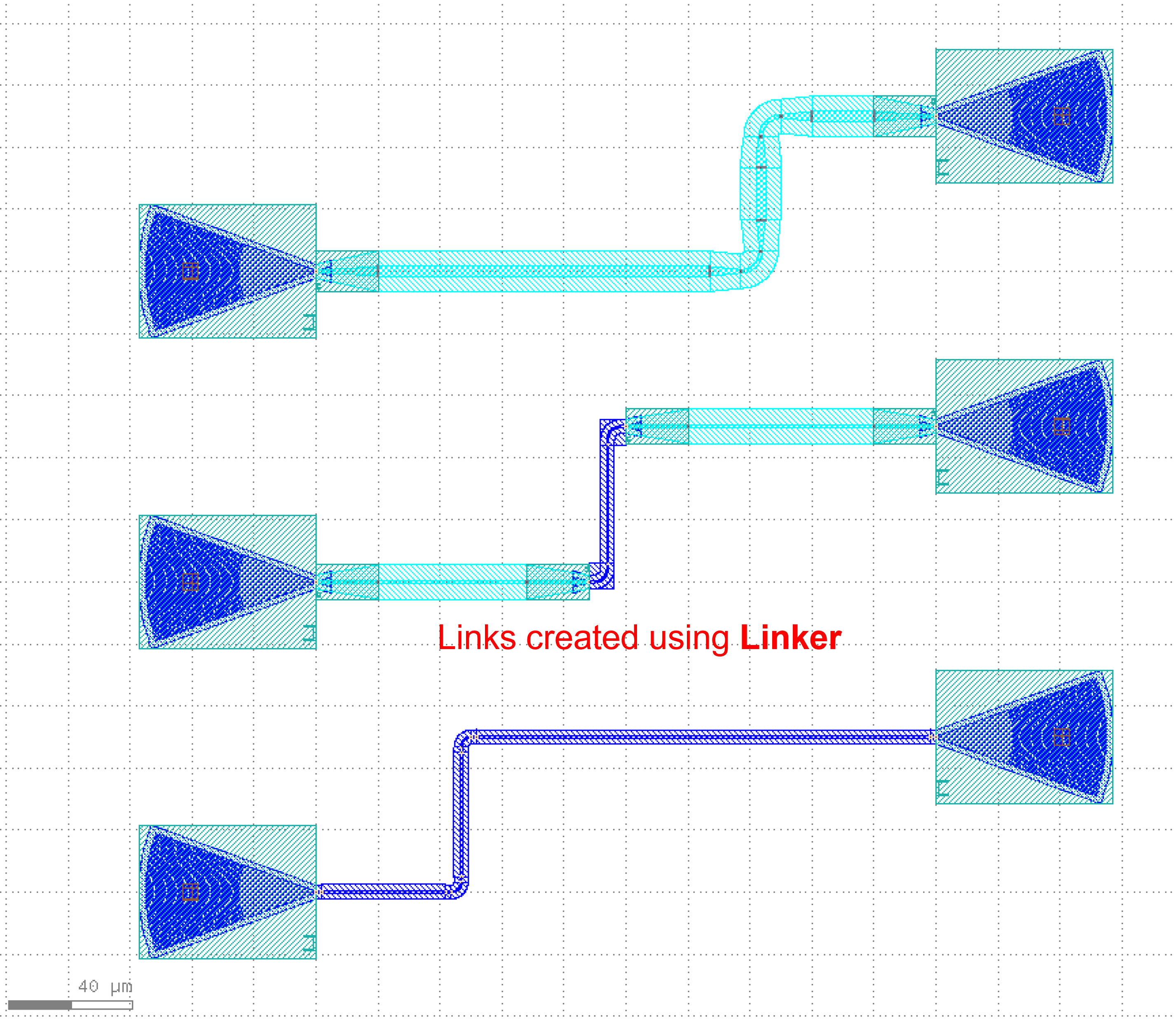
fp.create_links example ( Recommendation★★★★★ )
# Call the device
GC = pdk.GratingCoupler(waveguide_type=TECH.WG.FWG.C.WIRE)

# Place the device in different locations and add them to insts
gc1 = GC.h_mirrored().translated(-100, -100)
insts += gc1
gc2 = GC.h_mirrored().translated(-100, 0)
insts += gc2
gc3 = GC.h_mirrored().translated(-100, 100)
insts += gc3
gc4 = GC.translated(100, -50)
insts += gc4
gc5 = GC.translated(100, 50)
insts += gc5
gc6 = GC.translated(100, 150)
insts += gc6

# Interconnecting device ports by calling the create_links method
device = fp.create_links(
    link_type=TECH.WG.FWG.C.EXPANDED,  # Define the type of straight waveguide in automatic routing
    bend_factory=TECH.WG.FWG.C.WIRE.BEND_CIRCULAR,  # Define the type of bend in automatic routing
    # Define the connection between device ports in specs
    specs=[
        gc1["op_0"] >> fp.Waypoint(-50, -50, 0) >> gc4["op_0"],  # Use >> to define connections between two ports
        gc2["op_0"] >> fp.Waypoint(0, 50, 0) >> gc5["op_0"],  # Use fp.Waypoint(x,y) to define the path point
        # Use LinkBetween to define a separate segment of the connection,
        # and you can modify the type of the straight waveguide and bend with parameters
        fp.LinkBetween(
            start=gc3["op_0"],
            end=gc6["op_0"],
            link_type=TECH.WG.SWG.C.EXPANDED,
            bend_factory=TECH.WG.SWG.C.WIRE.BEND_CIRCULAR,
            waypoints=[fp.Waypoint(50, 150, 0)]
        )
    ],
)
# Get and print the length of the three connected links
length_1 = device[0].curve_length
length_2 = device[1].curve_length
length_3 = device[2].curve_length
print(f"{length_1} \n {length_2} \n {length_3}")

insts += device  # Add the device returned by create_links to insts
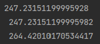
The message box shows that the lengths of each of the three connected links are printed.
Routing Path Selection
There are two ways to choose a path.
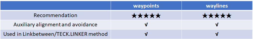
waypointswaylines
waypoints and waylines are used as parameters in the routing method to aid in waveguide alignment and avoidance, however, they cannot be used at the same time;
waypoints can set the turning angle. If you have determined that the waveguide needs to pass through some points, you can use waypoints, waylines can be more concise to do 90 degrees of turning.
Here’s a comparison of the two options
waylines
Absolute control points provided
device = fp.LinkBetween(
    start=gc1["op_0"],
    end=gc2["op_0"],
    link_type=TECH.WG.SWG.C.EXPANDED,
    bend_factory=TECH.WG.SWG.C.WIRE.BEND_CIRCULAR,
    # By setting waylines so that the waveguide passes through the x=-50, y=50 and x=50 lines in turn
    waylines=[fp.until_x(-50), fp.until_y(50), fp.until_x(50)]
)
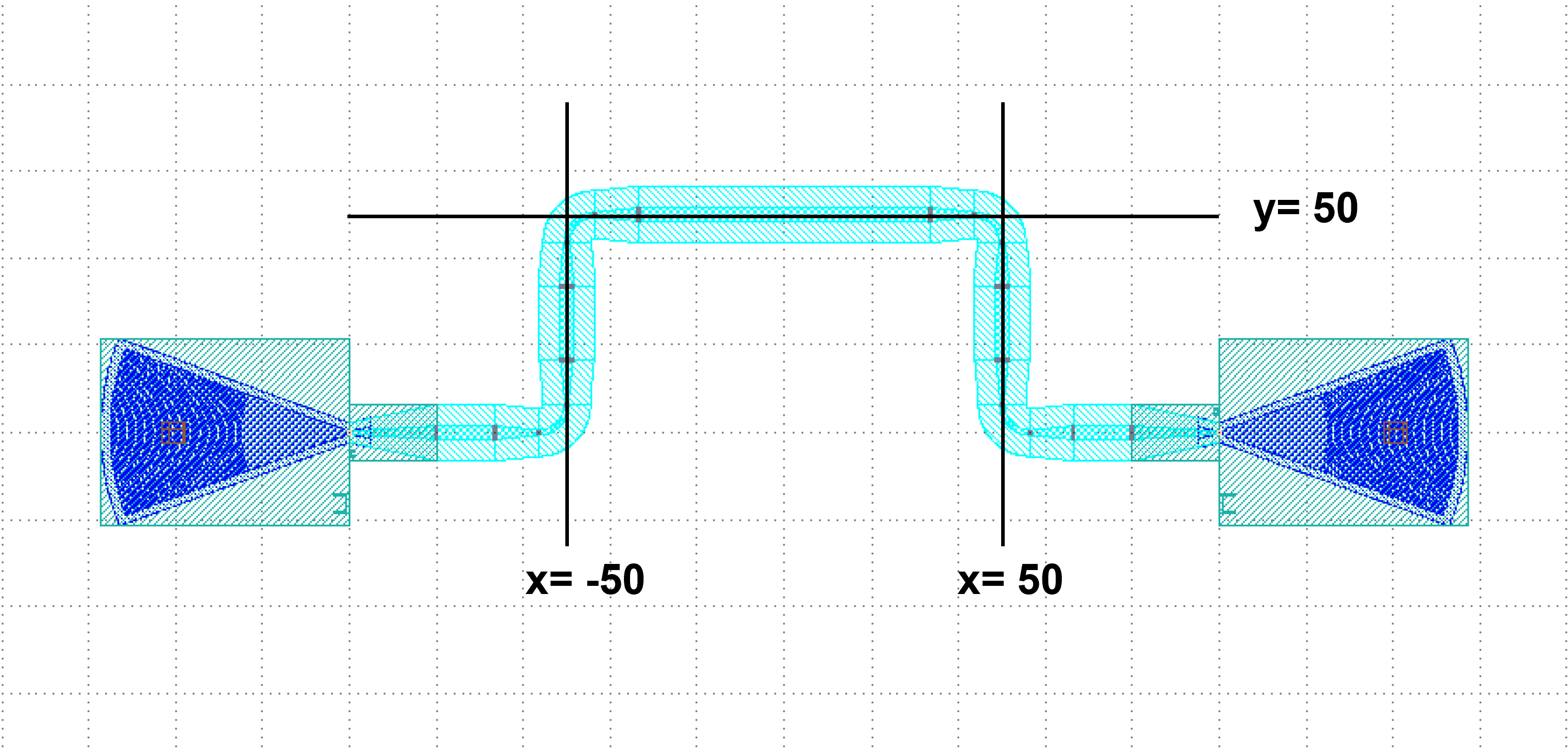
By setting waylines , we can control the waveguide first passes through the line x=-50 and then through the lines y=50, x=50.
Relative control points provided
device = fp.LinkBetween(
    start=gc1["op_0"],
    end=gc2["op_0"],
    link_type=TECH.WG.FWG.C.WIRE,
    bend_factory=TECH.WG.FWG.C.WIRE.BEND_CIRCULAR,
    waylines=[
        fp.until_x(x=-100),  # Pass through the line x = -100
        fp.until_y(y=fp.START+100),  # Take the vertical coordinate Y of the starting port, where Y=0, and pass through the line y=Y+100
        fp.until_x(x=fp.PREV+100),  # Take the horizontal coordinate X of the last turn, here X = -100, and pass through the line x = X + 100
        fp.until_y(y=fp.END+50),  # Take the vertical coordinate Y of the termination port, where Y=0, and pass through the line y=Y+50
        fp.until_x(x=fp.PREV+100)  # Take the horizontal coordinate X of the last turn, where X=0, and pass through the line x=X+100
              ]
)
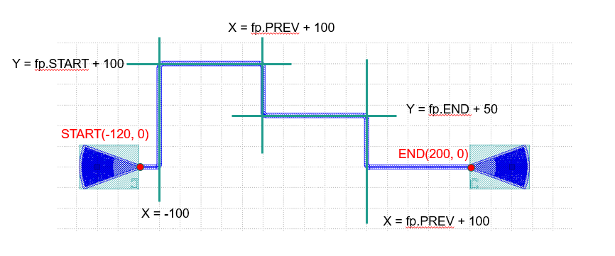
Here fp.END is used to get the position of the ending port, and similarly fp.START can be used to get the position of the starting port. Use fp.PREV to get the position of the previous turning point, which allows the user to design based on the previous turning point.
waypoints
device = fp.LinkBetween(
    start=gc1["op_0"],
    end=gc2["op_0"],
    link_type=TECH.WG.SWG.C.EXPANDED,
    bend_factory=TECH.WG.SWG.C.WIRE.BEND_CIRCULAR,
    # Set waypoints to guide the waveguide through the path points, the three values in the fp.Waypoints brackets represent x,y,angle respectively.
    waypoints=[
       fp.Waypoint(-50, 10, 90),
       fp.Waypoint(0, 50, 0),
       fp.Waypoint(50, 10, -90)]
)

insts += device
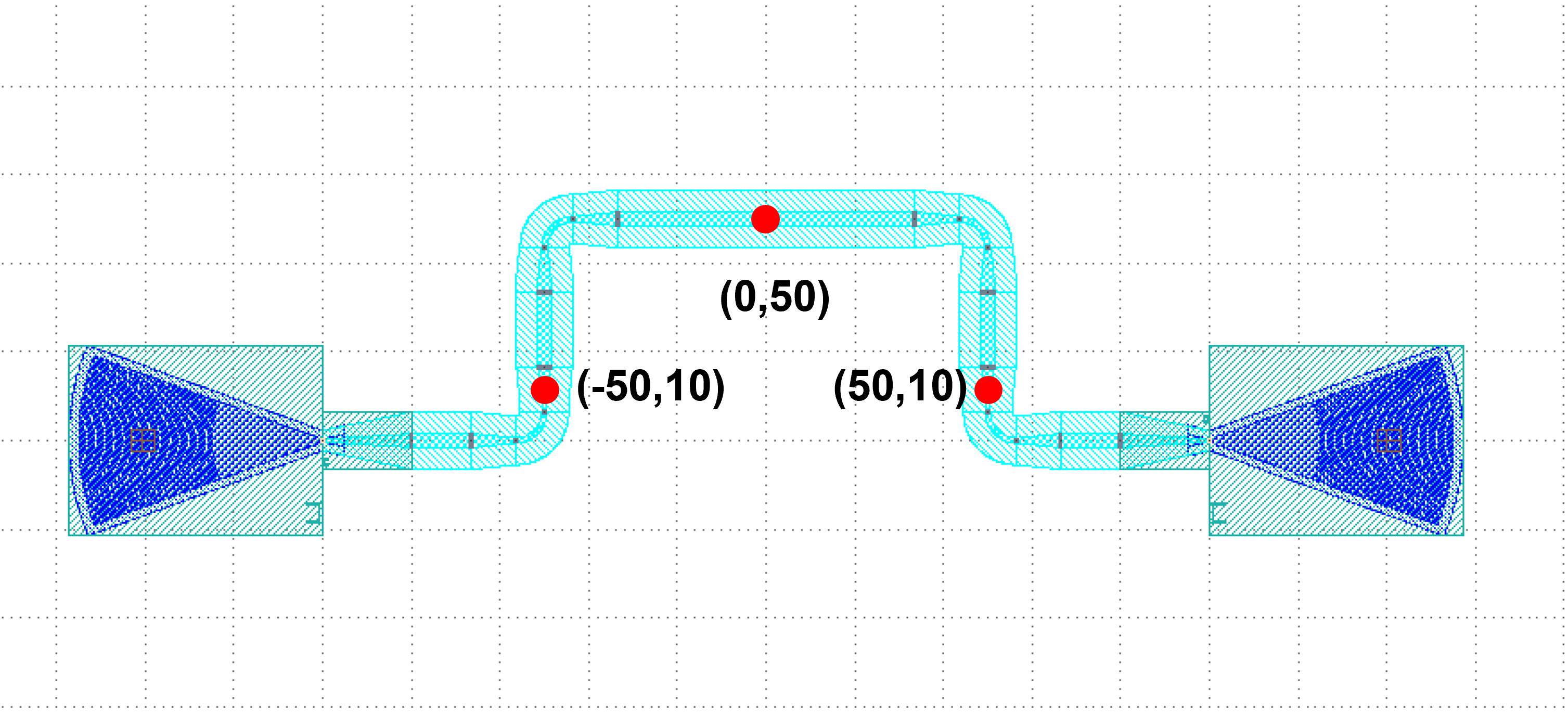
Set waypoints to guide the waveguide through the control points. The three values in the fp.Waypoint brackets represent x,``y``,``angle`` respectively.
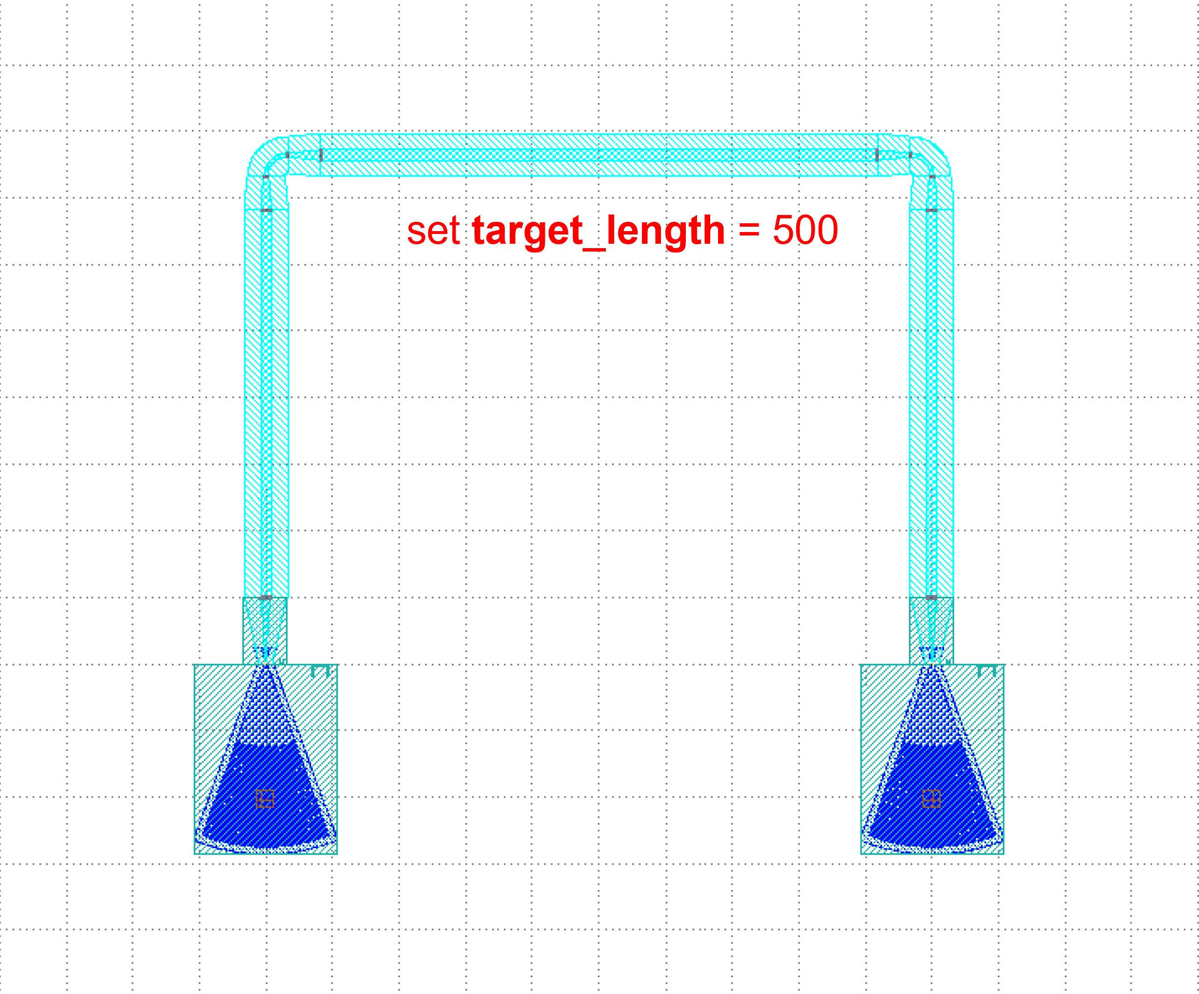
For the case where the two ports are connected in U-shape, the length can be defined by setting the target_length parameter in LinkBetween and LINKER, and the waveguide will automatically extend the straight waveguide to the corresponding length, where target_length is the total length of the entire wiring waveguide.
target_length
device = fp.LinkBetween(
    start=gc1["op_0"],
    end=gc2["op_0"],
    link_type=TECH.WG.SWG.C.EXPANDED,
    bend_factory=TECH.WG.SWG.C.WIRE.BEND_CIRCULAR,
    # set target_length
    target_length=500
)

insts += device