Step 3: Build complex circuits using basic building blocks
In Step2(Step 2: Build basic circuits with basic building blocks), we have built the basic circuit using the basic building blocks. In this section, we continue to build some complex circuits through the connection of these basic circuits to achieve more functionality, such as the MZI circuit. The connections between the basic circuits are provided in three main ways:
In the following, we will start from these three connection types and use each of them to build a MZI circuit.
target_length
Import the directed coupler created in step 2(Step 2: Build basic circuits with basic building blocks):
from step.step2.directional_coupler_bend import DirectionalCouplerBend
Define the MZI class to easily call directly later:
class MZI(fp.PCell):

    def build(self):
        insts, elems, ports = super().build()
        TECH = get_technology()

        dc = DirectionalCouplerBend(
            coupler_spacing=0.5,
            coupler_length=6,
            bend_radius=10,
            straight_after_bend=6,
            waveguide_type=TECH.WG.FWG.C.WIRE
        )
        dc1 = dc.translated(-100, 0)
        insts += dc1
        dc2 = dc.translated(100, 0)
        insts += dc2

        device = fp.create_links(
            link_type=TECH.WG.FWG.C.EXPANDED,
            bend_factory=TECH.WG.FWG.C.WIRE.BEND_CIRCULAR,
            specs=[
                fp.LinkBetween(
                    dc1["op_2"],
                    dc2["op_1"],
                    target_length=500,
                ),
                fp.LinkBetween(
                    dc1["op_3"],
                    dc2["op_0"],
                    target_length=320,
                ),
            ],
        )
        insts += device

        ports += dc1["op_0"].with_name("in1")
        ports += dc1["op_1"].with_name("in2")
        ports += dc2["op_2"].with_name("out1")
        ports += dc2["op_3"].with_name("out2")

        # fmt: on
        return insts, elems, ports
which:
device = fp.create_links(
    link_type=TECH.WG.FWG.C.EXPANDED,
    bend_factory=TECH.WG.FWG.C.WIRE.BEND_CIRCULAR,
    specs=[
        fp.LinkBetween(
            dc1["op_2"],
            dc2["op_1"],
            target_length=500,
        ),
        fp.LinkBetween(
            dc1["op_3"],
            dc2["op_0"],
            target_length=320,
        ),
    ],
)
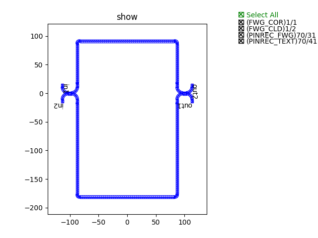
The U-shaped fixed-length connection is achieved by “target_length=320”.
Finally, generate the layout and plot by calling the class implementation:
device += MZI()
fp.export_gds(device, file=gds_file)
fp.plot(device)
Example of the MZI circuit connected by the U-shaped target length method
waypoints
Import the directed coupler created in step 2(Step 2: Build basic circuits with basic building blocks):
from step.step2.directional_coupler_bend import DirectionalCouplerBend
Define the MZI class to easily call directly later:
class MZI(fp.PCell):
    def build(self):
        insts, elems, ports = super().build()
        TECH = get_technology()

        dc = DirectionalCouplerBend(
            coupler_spacing=0.5,
            coupler_length=6,
            bend_radius=10,
            straight_after_bend=6,
            waveguide_type=TECH.WG.FWG.C.WIRE
        )
        dc1 = dc.translated(-100, 0)
        insts += dc1
        dc2 = dc.translated(100, 0)
        insts += dc2

        device = fp.create_links(
            link_type=TECH.WG.FWG.C.EXPANDED,
            bend_factory=TECH.WG.FWG.C.WIRE.BEND_CIRCULAR,
            specs=[
                fp.LinkBetween(
                    dc1["op_2"],
                    dc2["op_1"],
                    waypoints=[
                        fp.Waypoint(-50, -70, -90),
                        fp.Waypoint(0, -100, 0),
                        fp.Waypoint(50, -70, 90),
                    ]
                ),
                fp.LinkBetween(
                    dc1["op_3"],
                    dc2["op_0"],
                    waypoints=[
                        fp.Waypoint(-50, 70, 90),
                        fp.Waypoint(0, 100, 0),
                        fp.Waypoint(50, 70, -90),
                    ]
                ),
            ],
        )
        insts += device

        ports += dc1["op_0"].with_name("in1")
        ports += dc1["op_1"].with_name("in2")
        ports += dc2["op_2"].with_name("out1")
        ports += dc2["op_3"].with_name("out2")

        # fmt: on
        return insts, elems, ports
which:
device = fp.create_links(
    link_type=TECH.WG.FWG.C.EXPANDED,
    bend_factory=TECH.WG.FWG.C.WIRE.BEND_CIRCULAR,
    specs=[
        fp.LinkBetween(
            dc1["op_2"],
            dc2["op_1"],
            waypoints=[
                fp.Waypoint(-50, -70, -90),
                fp.Waypoint(0, -100, 0),
                fp.Waypoint(50, -70, 90),
            ]
        ),
        fp.LinkBetween(
            dc1["op_3"],
            dc2["op_0"],
            waypoints=[
                fp.Waypoint(-50, 70, 90),
                fp.Waypoint(0, 100, 0),
                fp.Waypoint(50, 70, -90),
            ]
        ),
    ],
)
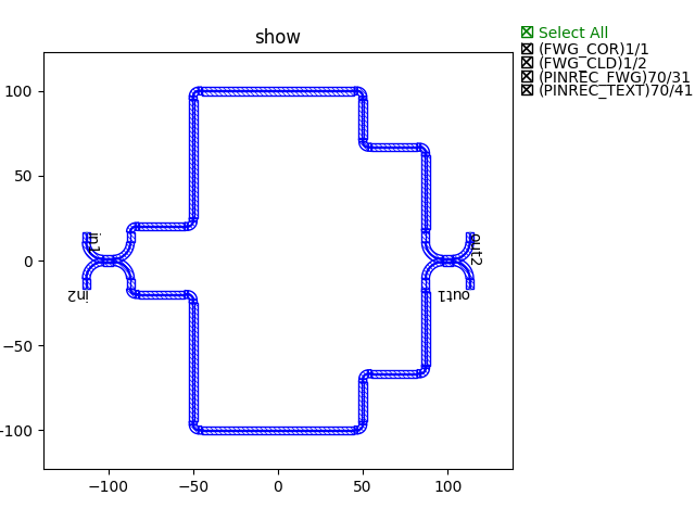
The route points are connected by “waypoints”, i.e. the route is connected through all set points.
Finally, generate the layout and plot by calling the class implementation:
device += MZI()
fp.export_gds(device, file=gds_file)
fp.plot(device)
Example of the MZI circuit connected by the waypoint method
waylines
Import the directed coupler created in step 2(Step 2: Build basic circuits with basic building blocks):
from step.step2.directional_coupler_bend import DirectionalCouplerBend
Define the MZI class to easily call directly later:
class MZI(fp.PCell):
def build(self):
insts, elems, ports = super().build()
TECH = get_technology()
dc = DirectionalCouplerBend(
coupler_spacing=0.5,
coupler_length=6,
bend_radius=10,
straight_after_bend=6,
waveguide_type=TECH.WG.FWG.C.WIRE
)
dc1 = dc.translated(-100, 0)
insts += dc1
dc2 = dc.translated(100, 0)
insts += dc2
device = fp.create_links(
link_type=TECH.WG.FWG.C.EXPANDED,
bend_factory=TECH.WG.FWG.C.WIRE.BEND_CIRCULAR,
specs=[
fp.LinkBetween(
dc1["op_2"],
dc2["op_1"],
waylines=[fp.until_y(-100)]
),
fp.LinkBetween(
dc1["op_3"],
dc2["op_0"],
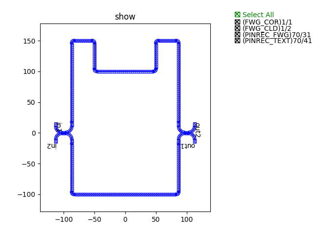
waylines=[fp.until_y(150),
fp.until_x(-50),
fp.until_y(100),
fp.until_x(50),
fp.until_y(150)]
),
],
)
insts += device
ports += dc1["op_0"].with_name("in1")
ports += dc1["op_1"].with_name("in2")
ports += dc2["op_2"].with_name("out1")
ports += dc2["op_3"].with_name("out2")
# fmt: on
return insts, elems, ports
which:
device = fp.create_links(
    link_type=TECH.WG.FWG.C.EXPANDED,
    bend_factory=TECH.WG.FWG.C.WIRE.BEND_CIRCULAR,
    specs=[
        fp.LinkBetween(
            dc1["op_2"],
            dc2["op_1"],
            waylines=[fp.until_y(-100)]
        ),
        fp.LinkBetween(
            dc1["op_3"],
            dc2["op_0"],
            waylines=[fp.until_y(150),
                      fp.until_x(-50),
                      fp.until_y(100),
                      fp.until_x(50),
                      fp.until_y(150)]
        ),
    ],
)
The pathlines are connected by “waylines”.
Finally, generate the layout and plot by calling the class implementation:
device += MZI()
fp.export_gds(device, file=gds_file)
fp.plot(device)
Example of the MZI circuit connected by the wayline method