Step 4: Drawing of common shapes and layout design by Boolean operations
This case shows the drawing of common graphics and the layout design of complex structures by Boolean operations.
The main contents of this section include:
First, the drawing of some commonly used shapes:
Boolean operations are an important design tool for layout design, especially for complex structures. Common inter-graph Boolean operations mainly include:
Commonly_used_shape
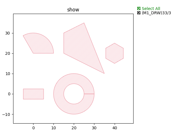
Rectangle
rect = fp.el.Rect(width=10, height=5, center=(0,0), layer=TECH.LAYER.M1_DRW)
Circle
circ = fp.el.Circle(radius=10, initial_degrees=0, final_degrees=120, layer=TECH.LAYER.M1_DRW)
Polygon
poly = fp.el.Polygon(raw_shape=[(-5, 0), (-5, 10), (5, 15), (15, -10)], layer=TECH.LAYER.M1_DRW)
Ring
ring = fp.el.Ring(inner_radius=5, outer_radius=10, layer=TECH.LAYER.M1_DRW)
Regular_Polygon
rpoly = fp.el.RegularPolygon(sides=6, side_length=5, layer=TECH.LAYER.M1_DRW)
The above examples are shown below:
Boolean_operation
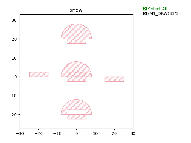
OR
bool = rect | circ
AND
bool = rect & circ
NOT
bool = rect - circ
XOR
bool = rect ^ circ
The above examples are shown below:
Full script:
from typing import Tuple

from fnpcell import all as fp
from gpdk.technology import get_technology


class Boolean(fp.IWaveguideLike, fp.PCell):
    def build(self) -> Tuple[fp.InstanceSet, fp.ElementSet, fp.PortSet]:
        insts, elems, ports = super().build()
        TECH = get_technology()

        rect = fp.el.Rect(width=10, height=5, center=(0,0), layer=TECH.LAYER.M1_DRW)
        elems += rect.translated(0, 0)
        circ = fp.el.Circle(radius=8, initial_degrees=0, final_degrees=180, layer=TECH.LAYER.M1_DRW)
        elems += circ.translated(0, 0)
        bool = rect - circ
        elems += bool.translated(20, 0)
        bool = rect & circ
        elems += bool.translated(-20, 0)
        bool = rect | circ
        elems += bool.translated(0, 20)
        bool = rect ^ circ
        elems += bool.translated(0, -20)

        return insts, elems, ports

if __name__ == "__main__":
    from pathlib import Path

    gds_file = Path(__file__).parent / "local" / Path(__file__).with_suffix(".gds").name
    library = fp.Library()

    TECH = get_technology()
    # =============================================================
    # fmt: off

    library += Boolean()

    # fmt: on
    # =============================================================
    fp.export_gds(library, file=gds_file)
    fp.plot(library)
Examples
Import step 3 (Step 1: Build basic building blocks) U-shaped target length MZI structure and plot:
class CircuitBool(fp.IWaveguideLike, fp.PCell):
def build(self) -> Tuple[fp.InstanceSet, fp.ElementSet, fp.PortSet]:
insts, elems, ports = super().build()
TECH = get_technology()
device = MZI()
ports += device.ports
insts += device
cor = device.polygon_set(layer=TECH.LAYER.FWG_COR)
# elems += cor
cld = device.polygon_set(layer=TECH.LAYER.FWG_CLD)
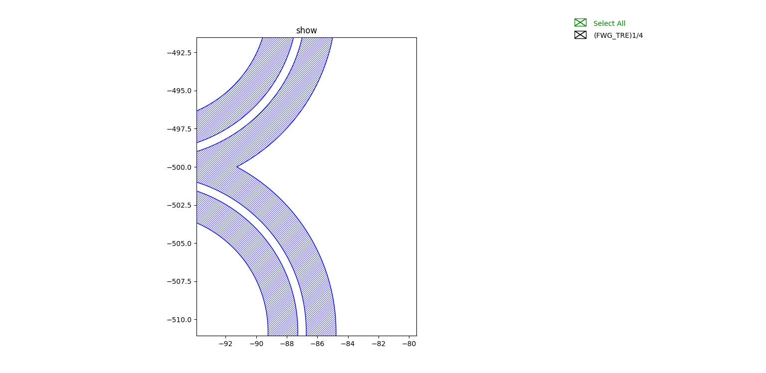
tre = fp.el.PolygonSet.boolean_sub(cld, cor, layer=TECH.LAYER.FWG_TRE)
elems += tre.translated(0, -500)
return insts, elems, ports
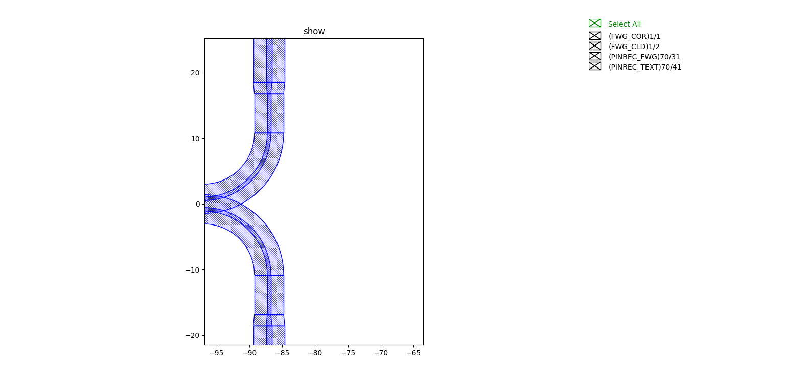
The above code implements two types of MZI circuits by Boolean operations, one containing all layer information and one for etched layer trenching, as shown in the figure:
Layout with all layer information:
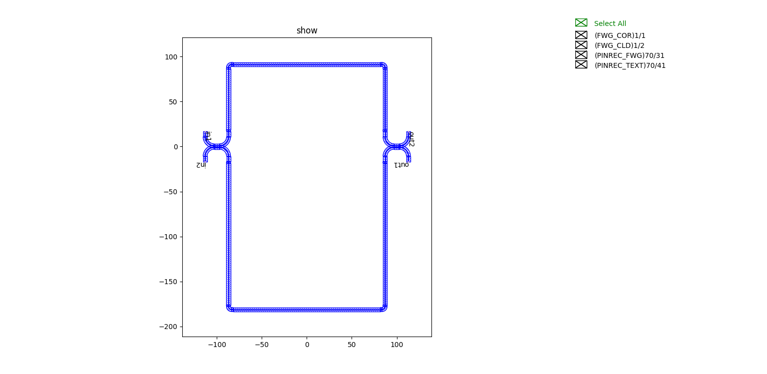
Partial display is as follows:
Etched layer trenching type circuit partial display: