Triangle MZI mesh
In addition to rectangular programmable photonic circuits, triangular network-based programmable photonic circuits have also been widely used. This section explains in detail how to build a triangular network programmable photonic link based on PhotoCAD starting from the unit element MZI.
Part I. Build MZI units
Before building the triangular mesh, the single components in the gpdk need to be supplemented. Here we choose to build a single arm tunable on-chip integrated MZI. The tunability of this device is achieved through a PN junction (electrically tunable), but of course a thermally tunable MZI can also be used to build this triangular mesh.
First, import the library file, where we need to use DirectionalCouplerSBend, Straight, PnPhaseShifter.
from typing import Tuple

from fnpcell import all as fp
from gpdk.components.directional_coupler.directional_coupler_sbend import DirectionalCouplerSBend
from gpdk.components.straight.straight import Straight
from gpdk.components.pn_phase_shifter.pn_phase_shifter import PnPhaseShifter
from gpdk.technology import WG, get_technology
Define the MZI class of the base single component of the mesh.
class MZI(fp.PCell, band="C"):
    p_width: float = fp.PositiveFloatParam(default=1)
    n_width: float = fp.PositiveFloatParam(default=1)
    np_offset: float = fp.FloatParam(default=0)
    wg_length: float = fp.PositiveFloatParam(default=100)
    arm_spacing: float = fp.PositiveFloatParam(default=60)
    dc_length: float = fp.FloatParam(default=100)
    waveguide_type: WG.FWG.C = fp.WaveguideTypeParam(type=WG.FWG.C)
    pn_phase_shifter: fp.IDevice = fp.DeviceParam(type=PnPhaseShifter, port_count=2, pin_count=2, required=False)
    straight_waveguide: fp.IDevice = fp.DeviceParam(type=Straight, port_count=2, required=False)
    directional_coupler_left: fp.IDevice = fp.DeviceParam(type=DirectionalCouplerSBend, port_count=4, required=False)
    directional_coupler_right: fp.IDevice = fp.DeviceParam(type=DirectionalCouplerSBend, port_count=4, required=False)
    port_names: fp.IPortOptions = fp.PortOptionsParam(count=4,default=["op_0", "op_1", "op_2", "op_3"])

    def _default_waveguide_type(self):
        return get_technology().WG.FWG.C.WIRE

    def _default_pn_phase_shifter(self):
        return PnPhaseShifter(
            name="ps", p_width=self.p_width, n_width=self.n_width, np_offset=self.np_offset,
            wg_length=self.wg_length-10, waveguide_type=self.waveguide_type,
            transform=fp.translate(5, 0)
        )
    def _default_straight_waveguide(self):
        return Straight(
            name="straight", waveguide_type=self.waveguide_type, length=self.wg_length, transform=fp.translate(0, -self.arm_spacing)
        )

    def _default_directional_coupler_left(self):
        return DirectionalCouplerSBend(
            name="dc_l", bend_radius=10, waveguide_type=self.waveguide_type, transform=fp.translate(-self.dc_length, -self.arm_spacing / 2)
        )

    def _default_directional_coupler_right(self):
        return DirectionalCouplerSBend(
            name="dc_r", bend_radius=10, waveguide_type=self.waveguide_type, transform=fp.translate(self.wg_length + self.dc_length, -self.arm_spacing / 2)
        )

    def build(self) -> Tuple[fp.InstanceSet, fp.ElementSet, fp.PortSet]:
        insts, elems, ports = super().build()
        # fmt: off

        waveguide_type = self.waveguide_type
        pn_phase_shifter = self.pn_phase_shifter.translated(-self.wg_length / 2, self.arm_spacing / 2)
        straight_waveguide = self.straight_waveguide.translated(-self.wg_length / 2, self.arm_spacing / 2)
        directional_coupler_left = self.directional_coupler_left.translated(-self.wg_length / 2, self.arm_spacing / 2)
        directional_coupler_right = self.directional_coupler_right.translated(-self.wg_length / 2, self.arm_spacing / 2)

        port_names = self.port_names
        ports += directional_coupler_left["op_0"].with_name(port_names[0])
        ports += directional_coupler_left["op_1"].with_name(port_names[1])
        ports += directional_coupler_right["op_2"].with_name(port_names[2])
        ports += directional_coupler_right["op_3"].with_name(port_names[3])

        insts += fp.Linked(
            link_type=waveguide_type,
            bend_factory=self.waveguide_type.BEND_EULER,
            links=[
                directional_coupler_left["op_3"] >> pn_phase_shifter["op_0"],
                directional_coupler_left["op_2"] >> straight_waveguide["op_0"],
                directional_coupler_right["op_0"] >> pn_phase_shifter["op_1"],
                directional_coupler_right["op_1"] >> straight_waveguide["op_1"],
            ],
            ports=[],
        )

        # fmt: on
        return insts, elems, ports
In this case, the MZI consists of two directional couplers, a phase shifter, and a straight waveguide, and the basic structure is shown in the following figure.
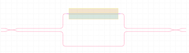
Among them, the phase shifter is built based on the PN structure, and by changing the voltage applied to both ends of the PN junction, the carrier concentration can be changed, thus changing the refractive index of the waveguide and eventually the relative phase. Thus, by varying the voltage, the MZI can be made to operate in different operating modes, such as bar, cross or couple, as shown in the following figure.

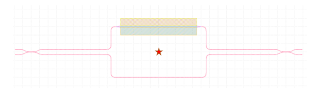
In this example, after building four single components in sequence and setting the location parameters, you can directly use PhotoCAD’s own Linked method to realize the automatic connection of ports. Next, you need to assign four ports to the MZI and specify the names. Note that we have panned each component in class so that the origin of the entire MZI cell is at the center of the MZI. If you do not do this, you will get an error when rotating the MZI, because the rotation operation in PhotoCAD is centered on the origin of a single component by default. The origin of the MZI in this example is shown in the following figure.
Call MZI in the main function and generate the gds file.
if __name__ == "__main__":
    from gpdk.util.path import local_output_file

    gds_file = local_output_file(__file__).with_suffix(".gds")
    library = fp.Library()

    TECH = get_technology()
    # =============================================================
    # fmt: off

    library += MZI()

    # fmt: on
    # =============================================================
    fp.export_gds(library, file=gds_file)
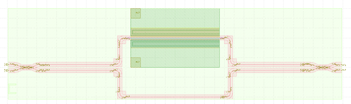
The automatically generated layout is as follows:
Part II. Build programmable triangular MZI mesh
In this step, the MZI class constructed in the previous step will be called to realize the construction of a triangular MZI mesh. We provide two implementations, one is the MZI mesh without grating couplers, which provides 8 external optical ports (op_0 ~ op_7), which can be easily customized to expand the network; the second implementation is to add 8 grating couplers to the MZI network, which constitutes a complete closed-loop photonic circuit layout.
MZI Mesh with 8 external optical ports (MZI_triangle_mesh)
First import the necessary library files.
from typing import Tuple

from fnpcell import all as fp
from gpdk.components.mzm.mzi import MZI
from gpdk.technology import WG, get_technology
from gpdk.routing.extended.extended import Extended
from gpdk.technology.waveguide_factory import EulerBendFactory
from gpdk.components.grating_coupler.grating_coupler import GratingCoupler
from gpdk.routing.comp_scan.comp_scan import CompScan,Block
Subsequently, the MZI_triangle_mesh class is constructed.
class MZI_triangle_mesh(fp.PCell, band="C"):
"""
Attributes:
p_width: defaults to 1
n_width: defaults to 1
np_offset: defaults to 0
wg_length: defaults to 25
arm_spacing: defaults to 100
dc_length: defaults to 100
waveguide_type: type of waveguide
pn_phase_shifter: instance of `PnPhaseShifter`, port_count=2, pin_count=2, required=False
straight_waveguide: instance of `Straight`, port_count=2, required=False
directional_coupler_left: instance of `DirectionalCouplerSBend`, port_count=2, required=False
directional_coupler_right: instance of `DirectionalCouplerSBend`, port_count=2, required=False
port_names: defaults to ["op_0", "op_1", "op_2", "op_3"]
Examples:
```python
TECH = get_technology()
mzi = MZI(wg_length=600, waveguide_type=TECH.WG.FWG.C.WIRE)
fp.plot(mzi)
```

"""
side_length: float = fp.PositiveFloatParam(default=400)
dc_length: float = fp.FloatParam(default=100)
arm_spacing: float = fp.FloatParam(default=60)
wg_length: float = fp.FloatParam(default=100)
waveguide_type: WG.FWG.C = fp.WaveguideTypeParam(type=WG.FWG.C)
MZI_unit: fp.IDevice = fp.DeviceParam(type=MZI, port_count=4, required=False)
port_names: fp.IPortOptions = fp.PortOptionsParam(count=8,
default=["op_0", "op_1", "op_2", "op_3", "op_4", "op_5", "op_6", "op_7"])
def _default_waveguide_type(self):
return get_technology().WG.FWG.C.WIRE
def _default_MZI_unit(self):
return MZI(arm_spacing=self.arm_spacing, dc_length=self.dc_length, wg_length=self.wg_length)
def build(self) -> Tuple[fp.InstanceSet, fp.ElementSet, fp.PortSet]:
insts, elems, ports = super().build()
# fmt: off
waveguide_type = self.waveguide_type
port_names = self.port_names
MZI_0 = self.MZI_unit.translated(0,0)
MZI_1 = self.MZI_unit.rotated(degrees=120).translated(self.side_length / 4, self.side_length / 4 * (3) ** (0.5))
MZI_2 = self.MZI_unit.rotated(degrees=60).translated(-self.side_length / 4, self.side_length / 4 * (3) ** (0.5))
MZI_3 = self.MZI_unit.translated(self.side_length / 2, self.side_length / 2 * (3) ** (0.5))
MZI_4 = self.MZI_unit.rotated(degrees=60).translated(self.side_length * 3 / 4, self.side_length / 4 * (3) ** (0.5))
ports += MZI_3["op_0"].with_name(port_names[0])
ports += MZI_2["op_3"].with_name(port_names[1])
ports += MZI_2["op_0"].with_name(port_names[2])
ports += MZI_0["op_1"].with_name(port_names[3])
ports += MZI_0["op_2"].with_name(port_names[4])
ports += MZI_4["op_1"].with_name(port_names[5])
ports += MZI_4["op_2"].with_name(port_names[6])
ports += MZI_3["op_3"].with_name(port_names[7])
insts += fp.Linked(
link_type=waveguide_type,
bend_factory=self.waveguide_type.BEND_EULER,
links=[
MZI_0["op_0"] >> MZI_2["op_1"],
MZI_0["op_3"] >> MZI_1["op_0"],
MZI_1["op_1"] >> MZI_4["op_0"],
MZI_4["op_3"] >> MZI_3["op_2"],
MZI_1["op_2"] >> MZI_3["op_1"],
MZI_1["op_3"] >> MZI_2["op_2"],
],
ports=[],
)
# fmt: on
return insts, elems, ports
In this section, we construct a triangular mesh photonic circuit based on five MZIs, and the eight ports and their labels have been labeled in the figure as follows:
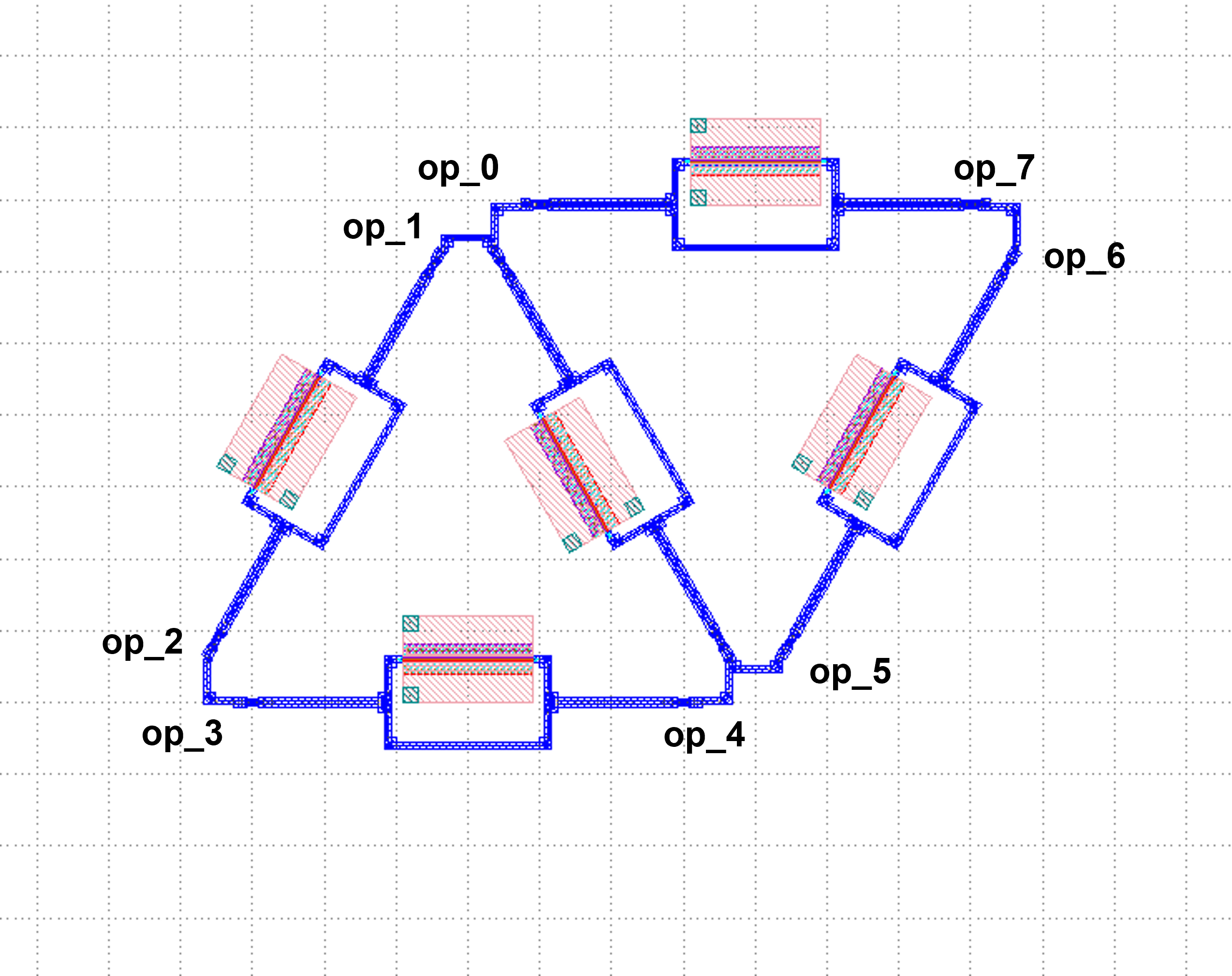
In the definition of this class we do not introduce the grating coupler, you need to define the grating coupler (or other types of couplers) in the main function; or you can also connect with other custom single components.
MZI Mesh with 8 Grating Couplers (MZI_triangle_mesh_with_GC)
Again, the necessary library files are imported first:
from typing import Tuple

from fnpcell import all as fp
from gpdk.components.mzm.mzi import MZI
from gpdk.technology import WG, get_technology
from gpdk.routing.extended.extended import Extended
from gpdk.technology.waveguide_factory import EulerBendFactory
from gpdk.components.grating_coupler.grating_coupler import GratingCoupler
from gpdk.routing.comp_scan.comp_scan import CompScan,Block
Subsequently, the MZI_triangle_mesh_with_GC class is constructed:
class MZI_triangle_mesh_with_GC(fp.PCell, band="C"):
"""
Attributes:
p_width: defaults to 1
n_width: defaults to 1
np_offset: defaults to 0
wg_length: defaults to 25
arm_spacing: defaults to 100
dc_length: defaults to 100
waveguide_type: type of waveguide
pn_phase_shifter: instance of `PnPhaseShifter`, port_count=2, pin_count=2, required=False
straight_waveguide: instance of `Straight`, port_count=2, required=False
directional_coupler_left: instance of `DirectionalCouplerSBend`, port_count=2, required=False
directional_coupler_right: instance of `DirectionalCouplerSBend`, port_count=2, required=False
port_names: defaults to ["op_0", "op_1", "op_2", "op_3"]
Examples:
```python
TECH = get_technology()
mzi = MZI(wg_length=600, waveguide_type=TECH.WG.FWG.C.WIRE)
fp.plot(mzi)
```

"""
side_length: float = fp.PositiveFloatParam(default=400)
dc_length: float = fp.FloatParam(default=100)
arm_spacing: float = fp.FloatParam(default=60)
wg_length: float = fp.FloatParam(default=100)
gc_spacing: float = fp.FloatParam(default=50)
waveguide_type: WG.FWG.C = fp.WaveguideTypeParam(type=WG.FWG.C)
MZI_unit: fp.IDevice = fp.DeviceParam(type=MZI, port_count=4, required=False)
grating_coupler: fp.IDevice = fp.DeviceParam(type=GratingCoupler, port_count=1, required=False)
def _default_waveguide_type(self):
return get_technology().WG.FWG.C.WIRE
def _default_MZI_unit(self):
return MZI(waveguide_type=self.waveguide_type, arm_spacing=self.arm_spacing,
dc_length=self.dc_length, wg_length=self.wg_length)
def _default_grating_coupler(self):
return GratingCoupler(waveguide_type=self.waveguide_type)
def build(self) -> Tuple[fp.InstanceSet, fp.ElementSet, fp.PortSet]:
insts, elems, ports = super().build()
# fmt: off
waveguide_type = self.waveguide_type
port_names = self.port_names
MZI_0 = self.MZI_unit.translated(0,0)
MZI_1 = self.MZI_unit.rotated(degrees=120).translated(self.side_length / 4, self.side_length / 4 * (3) ** (0.5))
MZI_2 = self.MZI_unit.rotated(degrees=60).translated(-self.side_length / 4, self.side_length / 4 * (3) ** (0.5))
MZI_3 = self.MZI_unit.translated(self.side_length / 2, self.side_length / 2 * (3) ** (0.5))
MZI_4 = self.MZI_unit.rotated(degrees=60).translated(self.side_length * 3 / 4, self.side_length / 4 * (3) ** (0.5))
gc_0 = self.grating_coupler.rotated(degrees=180).translated(-self.side_length / 4 * 3, -self.gc_spacing)
gc_1 = self.grating_coupler.rotated(degrees=180).translated(-self.side_length / 4 * 3, 10)
gc_2 = self.grating_coupler.rotated(degrees=180).translated(-self.side_length / 4 * 3, self.side_length / 2 * (3) ** (0.5) - 10 )
gc_3 = self.grating_coupler.rotated(degrees=180).translated(-self.side_length / 4 * 3, self.side_length / 2 * (3) ** (0.5) + self.gc_spacing)
gc_4 = self.grating_coupler.translated(-self.side_length / 4 * 3 + self.side_length * 2, -self.gc_spacing)
gc_5 = self.grating_coupler.translated(-self.side_length / 4 * 3 + self.side_length * 2, 10)
gc_6 = self.grating_coupler.translated(-self.side_length / 4 * 3 + self.side_length * 2,
self.side_length / 2 * (3) ** (0.5) - 10)
gc_7 = self.grating_coupler.translated(-self.side_length / 4 * 3 + self.side_length * 2,
self.side_length / 2 * (3) ** (0.5) + self.gc_spacing)
insts += fp.Linked(
link_type=waveguide_type,
bend_factory=self.waveguide_type.BEND_EULER,
links=[
MZI_0["op_1"] >> gc_0["op_0"],
MZI_2["op_0"] >> gc_1["op_0"],
MZI_2["op_3"] >> gc_2["op_0"],
MZI_3["op_0"] >> gc_3["op_0"],
MZI_0["op_2"] >> gc_4["op_0"],
MZI_4["op_1"] >> gc_5["op_0"],
MZI_4["op_2"] >> gc_6["op_0"],
MZI_3["op_3"] >> gc_7["op_0"],
MZI_0["op_0"] >> MZI_2["op_1"],
MZI_0["op_3"] >> MZI_1["op_0"],
MZI_1["op_1"] >> MZI_4["op_0"],
MZI_4["op_3"] >> MZI_3["op_2"],
MZI_1["op_2"] >> MZI_3["op_1"],
MZI_1["op_3"] >> MZI_2["op_2"],
],
ports=[],
)
# fmt: on
return insts, elems, ports
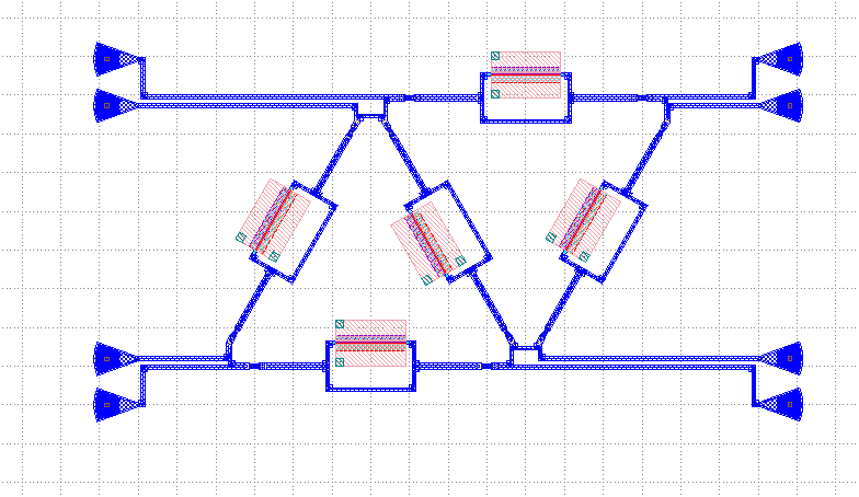
In this script contains the following parts:
First, default parameters are set, such as waveguide_type, GratingCoupler, etc.; then each single component is instantiated, including five MZI and eight GratingCoupler, and the coordinates and rotation angle are defined during the instantiation process. In this part, the coordinate settings of the GratingCoupler need to be fine-tuned to avoid the generation of flylines. In addition, the side_length of the triangular network and the gc_spacing of the GratingCoupler are adjustable in this example. Subsequently, the devices are connected by the Linked method.
Finally the gds file is generated in the main function.
if __name__ == "__main__":
    from gpdk.util.path import local_output_file

    gds_file = local_output_file(__file__).with_suffix(".gds")
    library = fp.Library()

    TECH = get_technology()
    # =============================================================
    # fmt: off

    mesh = MZI_triangle_mesh_with_GC()
    library += mesh

    # fmt: on
    # =============================================================
    fp.export_gds(library, file=gds_file)
The automatically generated layout is as follows:
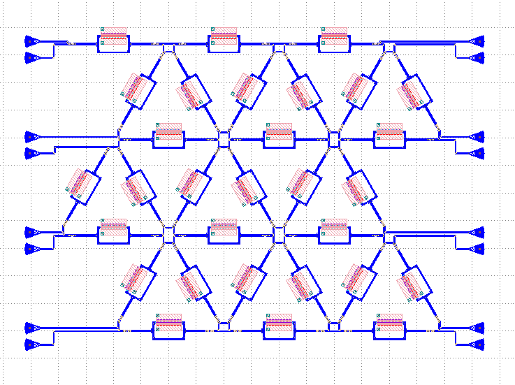
Triangle MZI array (MZI_triangle_array)
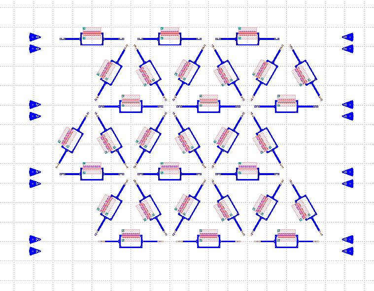
In this section, we upgrade the level of freedom of building the MZI array by setting col & row in the script. row represents the amount of triangle in the layout; col means how many GratingCoupler set will be generated in the layout.
The first 5 for loops are to generate and position all component, including MZI, MZI_60, MZI_120, gc_left and gc_right. MZI_60 and MZI_120 represents the rotation of the MZI coompare to MZI. gc_left and gc_right` represents the ``GratingCoupler which is located at the left or right side of the circuit. After the generation of each set of components, mzi = cast(Mapping[str, fp.ICellRef], insts) is to put those components to mzi for further use.
for i in range(row):
    for j in range(column):
        if j % 2:
            MZI = self.MZI_unit.translated(self.side_length * 2 * i / 2, self.side_length * j / 2 * (3) ** (0.5))
        else:
            MZI = self.MZI_unit.translated(self.side_length / 2+ self.side_length * 2 * i / 2, self.side_length * j / 2 * (3) ** (0.5))
        insts += MZI, f"MZI_{i},{j}"

for i in range(row):
    for j in range(column-1):
        if j % 2:
            MZI_rotate_60 = self.MZI_unit.rotated(degrees=60).translated(self.side_length * ((-1) + 4 * i) / 4, self.side_length * (2*j+1) / 4 * (3) ** (0.5))
        else:
            MZI_rotate_60 = self.MZI_unit.rotated(degrees=60).translated(self.side_length * ((1) + 4 * i) / 4, self.side_length * (2*j+1) / 4 * (3) ** (0.5))
        insts += MZI_rotate_60, f"MZI_60_{i},{j}"

for i in range(row):
    for j in range(column-1):
        if j % 2:
            MZI_rotate_120 = self.MZI_unit.rotated(degrees=120).translated(self.side_length * ((1)+4 * i) / 4, self.side_length * (2*j+1) / 4 * (3) ** (0.5))
        else:
            MZI_rotate_120 = self.MZI_unit.rotated(degrees=120).translated(self.side_length * ((3)+4 * i) / 4, self.side_length * (2*j+1) / 4 * (3) ** (0.5))
        insts += MZI_rotate_120, f"MZI_120_{i},{j}"
mzi = cast(Mapping[str, fp.ICellRef], insts)

for i in range(column):
    for j in range(2):
        gc = self.grating_coupler.rotated(degrees=180).translated(mzi[f"MZI_0,0"]["op_1"].position[0]-300, -self.gc_spacing + (self.gc_spacing+10)*j+self.side_length*i / 2 * (3) ** (0.5))
        insts += gc, f"gc_left_{i},{j}"

for i in range(column):
    for j in range(2):
        gc = self.grating_coupler.translated(mzi[f"MZI_0,1"]["op_1"].position[0]+self.side_length*row+250, -self.gc_spacing + (self.gc_spacing+10)*j+self.side_length*i / 2 * (3) ** (0.5))
        insts += gc, f"gc_right_{i},{j}"

mzi = cast(Mapping[str, fp.ICellRef], insts)
Here we set row=3, col=4 and the components are being positioned:
Next, the LinkBetween function is used to connect the optical ports, TECH.WG.FWG.C.WIRE and TECH.WG.FWG.C.WIRE.BEND_EULER are set to be default type of the waveguide and bend, respectively. Due to the complexity of the connection through each port, several for loops are used in the script to achieve auto-routing no matter the size of the circuit.
# bot & top line
for i in range(row-1):
    for j in range(column):
        if j == 0 :
            link1 = fp.LinkBetween(
                start = mzi[f"MZI_{i},{j}"]["op_2"],
                end= mzi[f"MZI_{i+1},{j}"]["op_1"],
                link_type=TECH.WG.FWG.C.WIRE,
                bend_factory=TECH.WG.FWG.C.WIRE.BEND_EULER
                )
            insts += link1
        if j == column-1:
            link2 = fp.LinkBetween(
                start=mzi[f"MZI_{i},{j}"]["op_3"],
                end=mzi[f"MZI_{i + 1},{j}"]["op_0"],
                link_type=TECH.WG.FWG.C.WIRE,
                bend_factory=TECH.WG.FWG.C.WIRE.BEND_EULER
            )
            insts += link2

# 60&120 turning
for i in range(row):
    for j in range(column - 1):
        if i < row:
            link3 = fp.LinkBetween(
                start=mzi[f"MZI_60_{i},{j}"]["op_2"],
                end=mzi[f"MZI_120_{i},{j}"]["op_3"],
                link_type=TECH.WG.FWG.C.WIRE,
                bend_factory=TECH.WG.FWG.C.WIRE.BEND_CIRCULAR
            )
            insts += link3
        if i < row-1:
            link4 = fp.LinkBetween(
                start=mzi[f"MZI_60_{i+1},{j}"]["op_0"],
                end=mzi[f"MZI_120_{i},{j}"]["op_1"],
                link_type=TECH.WG.FWG.C.WIRE,
                bend_factory=TECH.WG.FWG.C.WIRE.BEND_CIRCULAR
            )
            insts += link4

for i in range(row):
    for j in range(column-1):
        if (j % 2==0) or  (j ==0) :
            link5 = fp.LinkBetween(
                start=mzi[f"MZI_60_{i},{j}"]["op_3"],
                end=mzi[f"MZI_{i},{j+1}"]["op_2"],
                link_type=TECH.WG.FWG.C.WIRE,
                bend_factory=TECH.WG.FWG.C.WIRE.BEND_CIRCULAR
            )
            insts += link5
for i in range(row-1):
    for j in range(column - 1):
        if j % 2==1:
            link6 = fp.LinkBetween(
                start=mzi[f"MZI_60_{i+1},{j}"]["op_3"],
                end=mzi[f"MZI_{i},{j + 1}"]["op_2"],
                link_type=TECH.WG.FWG.C.WIRE,
                bend_factory=TECH.WG.FWG.C.WIRE.BEND_CIRCULAR
            )
            insts += link6


for i in range(row-1):
    for j in range(column - 1):
        if j % 2:
            link7 = fp.LinkBetween(
                start=mzi[f"MZI_120_{i},{j}"]["op_2"],
                end=mzi[f"MZI_{i},{j+1}"]["op_1"],
                link_type=TECH.WG.FWG.C.WIRE,
                bend_factory=TECH.WG.FWG.C.WIRE.BEND_CIRCULAR
            )
            insts += link7
        else:
            link8 = fp.LinkBetween(
                start=mzi[f"MZI_120_{i},{j}"]["op_2"],
                end=mzi[f"MZI_{i+1},{j + 1}"]["op_1"],
                link_type=TECH.WG.FWG.C.WIRE,
                bend_factory=TECH.WG.FWG.C.WIRE.BEND_CIRCULAR
            )
            insts += link8

for j in range(column-1):
    if j % 2:
        linkright = fp.LinkBetween(
            start=mzi[f"MZI_120_{row-1},{j}"]["op_2"],
            end=mzi[f"MZI_{row-1},{j + 1}"]["op_1"],
            link_type=TECH.WG.FWG.C.WIRE,
            bend_factory=TECH.WG.FWG.C.WIRE.BEND_CIRCULAR
        )
        insts += linkright

for i in range(row):
    for j in range(column-1):
        link9 = fp.LinkBetween(
            start=mzi[f"MZI_{i},{j}"]["op_0"],
            end=mzi[f"MZI_60_{i},{j}"]["op_1"],
            link_type=TECH.WG.FWG.C.WIRE,
            bend_factory=TECH.WG.FWG.C.WIRE.BEND_CIRCULAR
        )
        insts += link9
        link10 = fp.LinkBetween(
            start=mzi[f"MZI_{i},{j}"]["op_3"],
            end=mzi[f"MZI_120_{i},{j}"]["op_0"],
            link_type=TECH.WG.FWG.C.WIRE,
            bend_factory=TECH.WG.FWG.C.WIRE.BEND_CIRCULAR
        )
        insts += link10


for i in range(column-1):
    linkgcleft_1 = fp.LinkBetween(
        start=mzi[f"gc_left_{i},1"]["op_0"],
        end=mzi[f"MZI_60_0,{i}"]["op_0"],
        link_type=TECH.WG.FWG.C.WIRE,
        bend_factory=TECH.WG.FWG.C.WIRE.BEND_CIRCULAR,
    )
    insts += linkgcleft_1

for i in range(column-1):
    if i % 2 ==0:
        linkgcleft_2 = fp.LinkBetween(
            start=mzi[f"gc_left_{i+1},0"]["op_0"],
            end=mzi[f"MZI_0,{i+1}"]["op_1"],
            link_type=TECH.WG.FWG.C.WIRE,
            bend_factory=TECH.WG.FWG.C.WIRE.BEND_CIRCULAR,
            waypoints=[
                fp.Waypoint(mzi[f"gc_left_{i+1},0"]["op_0"].position[0] + 50,
                            mzi[f"MZI_0,{i+1}"]["op_1"].position[1],
                            0)
            ]

        )
        insts += linkgcleft_2
for i in range(column-1):
    if i % 2 == 1:
        linkgcleft_3 = fp.LinkBetween(
            start=mzi[f"gc_left_{i+1},0"]["op_0"],
            end=mzi[f"MZI_60_0,{i}"]["op_3"],
            link_type=TECH.WG.FWG.C.WIRE,
            bend_factory=TECH.WG.FWG.C.WIRE.BEND_CIRCULAR,
            waypoints=[
                fp.Waypoint(mzi[f"gc_left_{i+1},0"]["op_0"].position[0] + 50,
                            mzi[f"MZI_60_0,{i}"]["op_3"].position[1],
                            90)
            ]

        )
        insts += linkgcleft_3


for i in range(column-1):
    linkgcright_1 = fp.LinkBetween(
        start=mzi[f"gc_right_{i},1"]["op_0"],
        end=mzi[f"MZI_120_{row-1},{i}"]["op_1"],
        link_type=TECH.WG.FWG.C.WIRE,
        bend_factory=TECH.WG.FWG.C.WIRE.BEND_CIRCULAR,
    )
    insts += linkgcright_1


linkgcleft_top = fp.LinkBetween(
    start=mzi[f"gc_left_{column-1},1"]["op_0"],
    end=mzi[f"MZI_0,{column-1}"]["op_0"],
    link_type=TECH.WG.FWG.C.WIRE,
    bend_factory=TECH.WG.FWG.C.WIRE.BEND_CIRCULAR,
)
insts += linkgcleft_top
linkgcleft_bot = fp.LinkBetween(
    start=mzi[f"gc_left_0,0"]["op_0"],
    end=mzi[f"MZI_0,0"]["op_1"],
    link_type=TECH.WG.FWG.C.WIRE,
    bend_factory=TECH.WG.FWG.C.WIRE.BEND_CIRCULAR,
    waypoints=[
        fp.Waypoint(mzi[f"gc_left_0,0"]["op_0"].position[0] + 50,
                    mzi[f"MZI_0,0"]["op_1"].position[1],
                    0)
    ]
)
insts += linkgcleft_bot
linkgcright_top = fp.LinkBetween(
    start=mzi[f"gc_right_{column - 1},1"]["op_0"],
    end=mzi[f"MZI_{row-1},{column - 1}"]["op_3"],
    link_type=TECH.WG.FWG.C.WIRE,
    bend_factory=TECH.WG.FWG.C.WIRE.BEND_CIRCULAR,
)
insts += linkgcright_top
linkgcright_bot = fp.LinkBetween(
    start=mzi[f"gc_right_0,0"]["op_0"],
    end=mzi[f"MZI_{row - 1},0"]["op_2"],
    link_type=TECH.WG.FWG.C.WIRE,
    bend_factory=TECH.WG.FWG.C.WIRE.BEND_CIRCULAR,
    waypoints=[
        fp.Waypoint(mzi[f"gc_right_0,0"]["op_0"].position[0]-50,
                    mzi[f"MZI_{row-1},0"]["op_2"].position[1],
                    -180)
    ]
)
insts += linkgcright_bot


for i in range(column-1):
    if i%2:
        linkgcright_2 = fp.LinkBetween(
            start=mzi[f"gc_right_{i+1},0"]["op_0"],
            end=mzi[f"MZI_{row - 1},{i+1}"]["op_2"],
            link_type=TECH.WG.FWG.C.WIRE,
            bend_factory=TECH.WG.FWG.C.WIRE.BEND_CIRCULAR,
            waypoints=[
                fp.Waypoint(mzi[f"gc_right_{i+1},0"]["op_0"].position[0] - 50,
                            mzi[f"MZI_{row - 1},{i+1}"]["op_2"].position[1],
                            -180)
            ]
        )
        insts += linkgcright_2
    else:
        linkgcright_3 = fp.LinkBetween(
            start=mzi[f"gc_right_{i + 1},0"]["op_0"],
            end=mzi[f"MZI_120_{row - 1},{i}"]["op_2"],
            link_type=TECH.WG.FWG.C.WIRE,
            bend_factory=TECH.WG.FWG.C.WIRE.BEND_CIRCULAR,
            waypoints=[
                fp.Waypoint(mzi[f"gc_right_{i + 1},0"]["op_0"].position[0] - 50,
                            mzi[f"MZI_{row - 1},{i+1}"]["op_2"].position[1],
                            -180)
            ]

        )
        insts += linkgcright_3
The automatically generated layout is as follows: