Routing automation between components ports
fp.Linked, a functional module for port routing automation, is included in PhotoCAD. This module automates the routing of components in a layout by defining port connections in a Python script. For ports that require waveguide transition, the tool automatically selects the appropriate waveguide transition unit to convert the different waveguide types. After running the script file, a local folder is created to store the generated GDS, netlist, etc.
Linked
Linked, a functional module for port routing automation, is included in PhotoCAD. This module automates the routing of devices in a layout by defining port linking relationships in a Python script. For ports that require waveguide transition, the tool automatically selects the appropriate waveguide transition unit to convert the different waveguide types. After running the script file, a local folder is created to store the generated GDS, netlist, etc.
This example uses a script to place several different types of waveguides, set the connection relationship between waveguide ports, and achieve automatic routing of different types of waveguides through Linked in PhotoCAD.
Full Script
Section Script Description
Import the functional modules and the gpdk package:
from fnpcell import all as fp
from gpdk import all as pdk
from gpdk.technology import get_technology
from gpdk.technology.waveguide_factory import EulerBendFactory
Define class
Linked:class Linked(fp.PCell):
Define build function to generate components
Parameters correspond to instances, graphics, and ports in the function module:
def build(self):
    insts, elems, ports = super().build()
Implemented the waveguide used to connect the component ports in the function using the
get_technology()module ingpdk:TECH = get_technology()
The
SBendmodule ingpdkcreates an S-shaped bend which is an Euler Bend, where parameters such asdistance,height,waveguide_typeandbend_factorycontrol the lateral distance of the two ports, the vertical distance of the two ports, waveguide type and the process of the bend, respectively. Parameters such asradius_min,l_maxandwaveguide_typecontrol the process of the generatedEulerBend:sbend = pdk.SBend(distance=100, height=-90, waveguide_type=TECH.WG.FWG.C.WIRE, bend_factory=EulerBendFactory(radius_min=15, l_max=35, waveguide_type=TECH.WG.FWG.C.WIRE))
Define four different types of straight waveguides through the
Straightmodule ingpdk, with the parameterslengthandwaveguide_typecontrolling the length and type of the straight waveguide, respectively:straight_fw = pdk.Straight(length=5, waveguide_type=TECH.WG.FWG.C.WIRE) straight_fe = pdk.Straight(length=5, waveguide_type=TECH.WG.FWG.C.EXPANDED) straight_mw = pdk.Straight(length=5, waveguide_type=TECH.WG.MWG.C.WIRE) straight_sw = pdk.Straight(length=5, waveguide_type=TECH.WG.SWG.C.WIRE)
Create six different devices from each of the four different types of waveguides defined below, and control the position of the device by the
translated(x,y)method; control the rotation angle of the device by therotated(degrees=n)methodsb10 = sbend.translated(-200, 0) s10 = straight_fw s15 = straight_fe.translated(100, 0) s20 = straight_sw.translated(200, 0) s30 = straight_mw.rotated(degrees=30).translated(300, 100) s40 = straight_fw.rotated(degrees=30).translated(50, 100)
Define the connection relationship between the ports by calling the
fp.Linkedmodule to achieve automatic routing and combine all waveguides used for device port connection asdevice. For example,sb10["op_1"] <= s10["op_0"]defines that theop_0port of devices10is connected to theop_1port ofsb10. The completed device has only two ports,op_0ofsb10andop_1ofs40:device = fp.Linked( link_type=TECH.WG.SWG.C.EXPANDED, bend_factory=TECH.WG.FWG.C.WIRE.BEND_EULER, #bend_factory, links=[ sb10["op_1"] >> s10["op_0"], s10["op_1"] >> s15["op_0"], s15["op_1"] >> s20["op_0"], s20["op_1"] >> s30["op_0"], s30["op_1"] >> s40["op_0"], ], ports=[sb10["op_0"], s40["op_1"]], )
Instantiate
device:insts += device
Returns the instance, element and port of the generated device:
return insts, elems, ports
Create layout units using class
Linked:if __name__ == "__main__": from gpdk.util.path import local_output_file gds_file = local_output_file(__file__).with_suffix(".gds") library = fp.Library() TECH = get_technology() # ============================================================= # fmt: off library += Linked() # fmt: on # ============================================================= fp.export_gds(library, file=gds_file) # fp.plot(library)
Export GDS Layout
Linked: Top Level Layout UnitLinked_x1: Subunits ofLinked, containingLinked_linksand other component modules.Linked_links:Automatically generated combinations of waveguides connecting ports of various types of components.SBend:Eulerbendof the generated S-shape defined in the script.Straight*: Define the generatedStraightwaveguide in the script.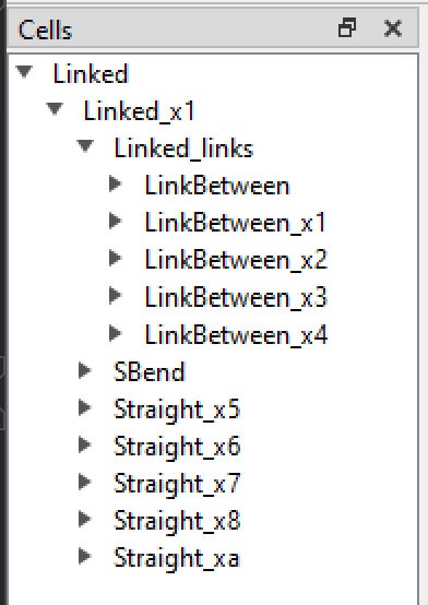
The
Linked_linksin the Cells list is a collection of waveguides automatically generated under theLinkedfunction. Double-click on theLinked_linksto hide them, and you can see in the layout the S-shapedEulerBendand the five straight waveguide shapes placed by the script, whose positions are realized in the script by.translate().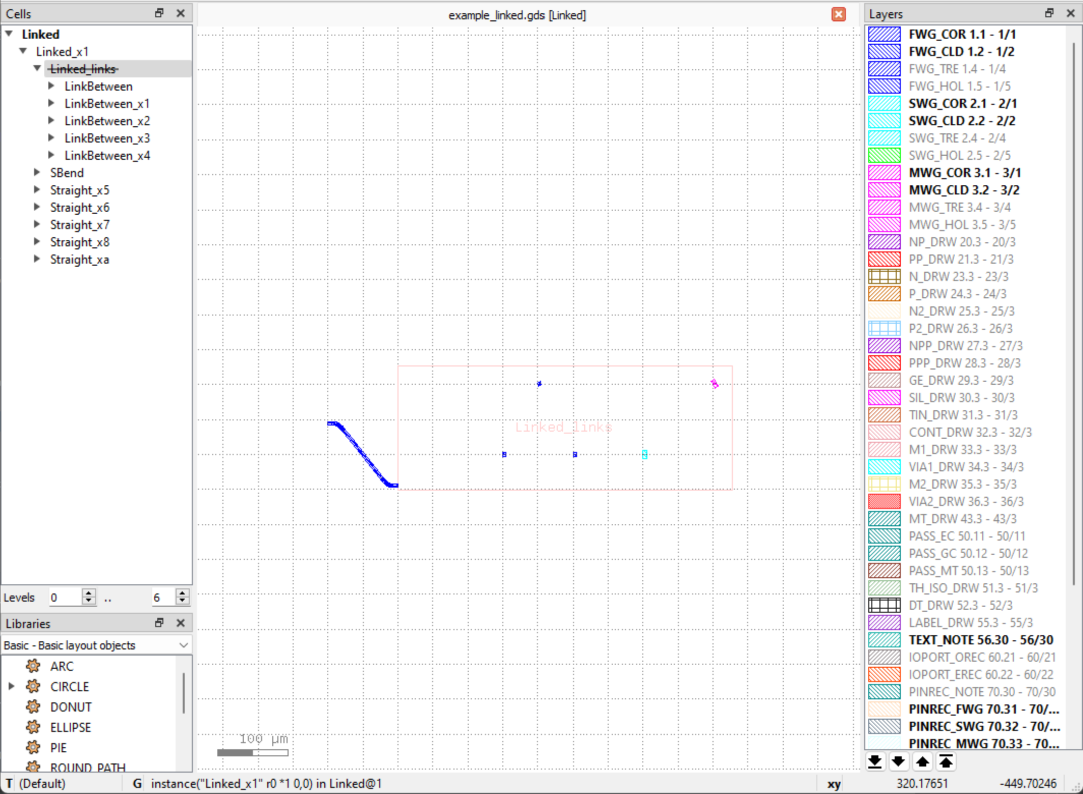
Double-click
Linked_linksagain to display it, and you can see that the connection waveguide generated by the script is adapted according to the port waveguide type, and the bend is automatically selected according to the port direction and angle to adjust the waveguide direction.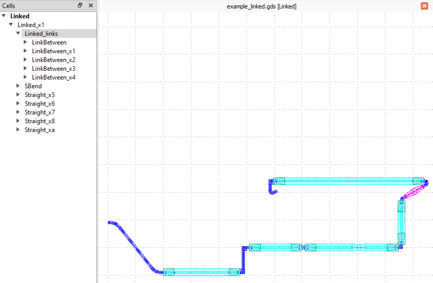
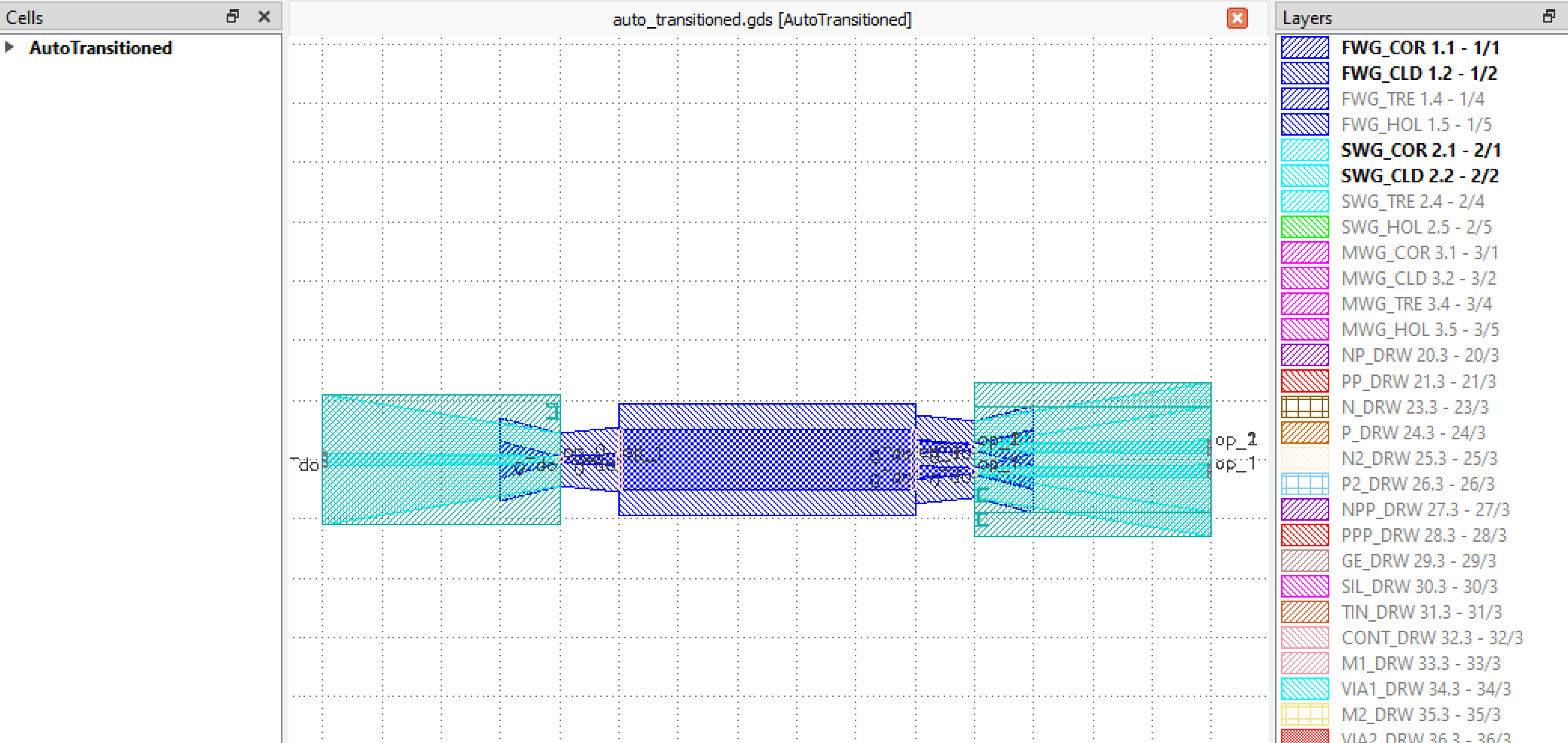
AutoTransitioned
In the case that the device ports need to connect to different types of waveguides, the AutoTransitioned method can be used to implement the transition of the component ports, and the specific schematic of this function is given in gpdk > routing > auto_transitioned > auto_transitioned.py, and the core usage is as follows
if __name__ == "__main__":
    from gpdk.util.path import local_output_file

    gds_file = local_output_file(__file__).with_suffix(".gds")
    library = fp.Library()

    TECH = get_technology()
    # =============================================================
    # fmt: off
    from gpdk.components.mmi.mmi import Mmi

    library += AutoTransitioned(device=Mmi(waveguide_type=TECH.WG.FWG.C.WIRE), waveguide_types={"*": TECH.WG.SWG.C.WIRE})

    # fmt: on
    # =============================================================
    fp.export_gds(library, file=gds_file)
    # fp.plot(library)
Here, different waveguide types of component ports are connected by using the AutoTransitioned class, where the parameter device is used to receive the components whose ports need to be automatically converted; waveguide_types receives the waveguide types of the converted ports, where *: TECH.WG.SWG.C.WIRE is a key-value pair and * refers to all undefined ports. Finally we can get the following device after port auto-transition.