Step 5: Example(MMI Tree)
This case uses the MMI circuit in Step 2 (Step 2: Build basic circuits with basic building blocks) to implement a cascade MMI tree and realize the layout drawing.
Import the MMI circuit created in Step 2 (Step 2: Build basic circuits with basic building blocks):
from step.step2.mmi1x2 import MMI1x2
Define the cascade MMI tree to easily call it directly later:
class MMITree(fp.PCell):
    def build(self):
        insts, elems, ports = super().build()
        TECH = get_technology()

        x_spacing = 50
        end_y_spacing = 50
        order = 2
        mmi = MMI1x2()
        num_per_col = []
        v_spacing = []

        for i in range(order):
            num_per_col.append(2**i)
            v_spacing.append(end_y_spacing*(2**(order - i - 1)))

        for i in range(order):
            for j in range(num_per_col[i]):
                x = i * x_spacing
                y = (-(num_per_col[i] - 1) * v_spacing[i]/2) + j * v_spacing[i]
                mmi = mmi["op_0"].repositioned(at=(x,y)).owner
                insts += mmi, f"{i},{j}"

        mmi_tree = cast(Mapping[str, fp.ICellRef], insts)
        for i in range(order):
            for j in range(num_per_col[i]):
                if i < order-1:
                    link1 = fp.LinkBetween(start=mmi_tree[f"{i},{j}"]["op_1"],
                                           end=mmi_tree[f"{i+1},{2*j}"]["op_0"],
                                           bend_factory=TECH.WG.FWG.C.WIRE.BEND_CIRCULAR)
                    insts += link1
                    link2 = fp.LinkBetween(start=mmi_tree[f"{i},{j}"]["op_2"],
                                           end=mmi_tree[f"{i+1},{2*j+1}"]["op_0"],
                                           bend_factory=TECH.WG.FWG.C.WIRE.BEND_CIRCULAR)
                    insts += link2

        ports += mmi_tree["0,0"]["op_0"].with_name("op_0")
        for i in range(num_per_col[-1]):
            ports += mmi_tree[f"{order - 1},{i}"]["op_1"].with_name(f"op_{2*i+1}")
            ports += mmi_tree[f"{order - 1},{i}"]["op_2"].with_name(f"op_{2*i+2}")

        # fmt: on
        return insts, elems, ports
Here the parameter “order”:
order = 2
This parameter indicates the level of the cascade, which in this case we take to be 4.
Call class and implement the layout by Boolean operations:
library += MMITree()
device = MMITree()
cor = device.polygon_set(layer=TECH.LAYER.FWG_COR)
cld = device.polygon_set(layer=TECH.LAYER.FWG_CLD)
tre = fp.el.PolygonSet.boolean_sub(cld, cor, layer=TECH.LAYER.FWG_TRE)
library += fp.Device(content=[tre.translated(300, 0)], ports=[])
fp.export_gds(library, file=gds_file)
fp.plot(library)
MMI tree cascade circuit plot
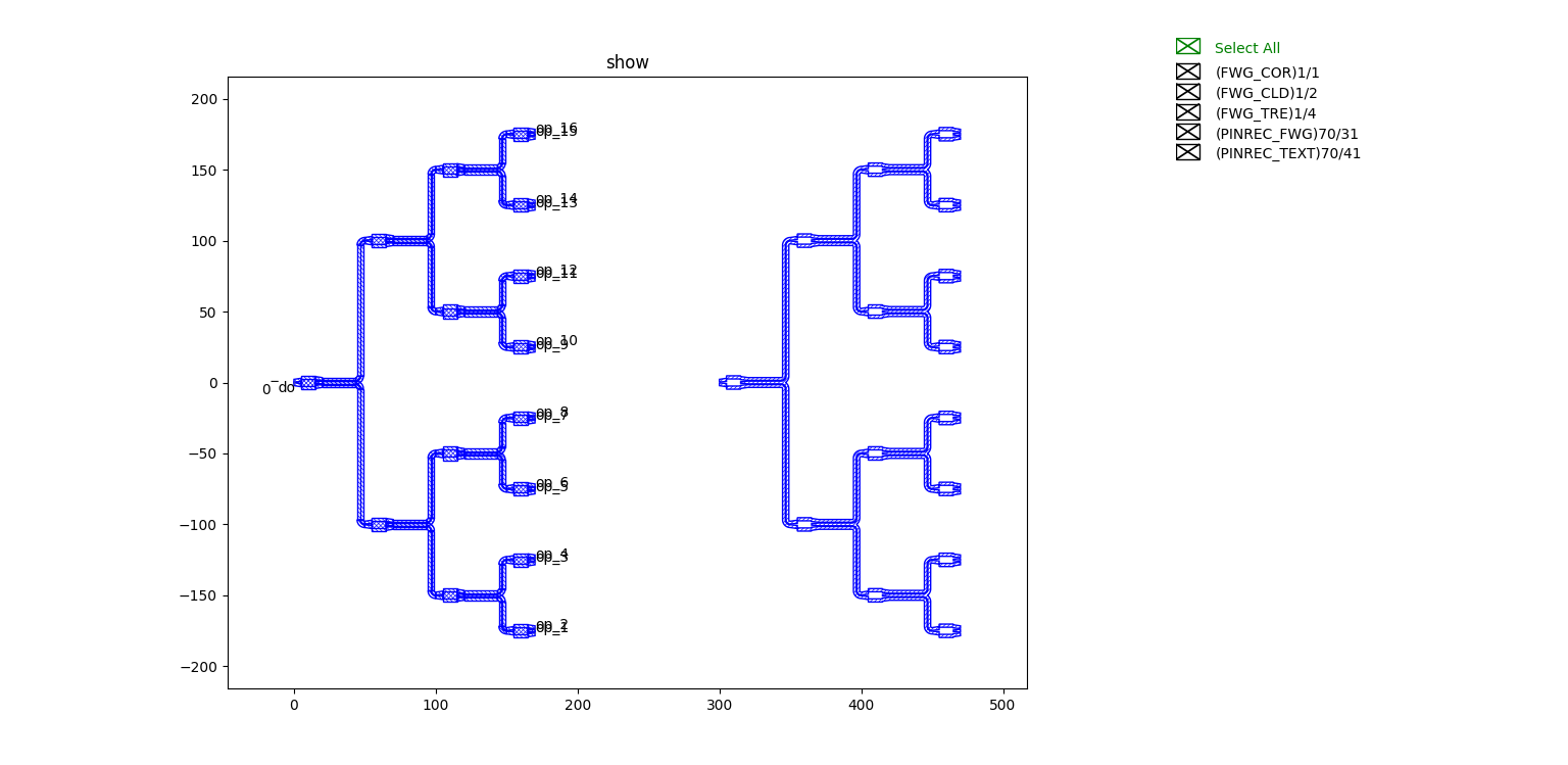
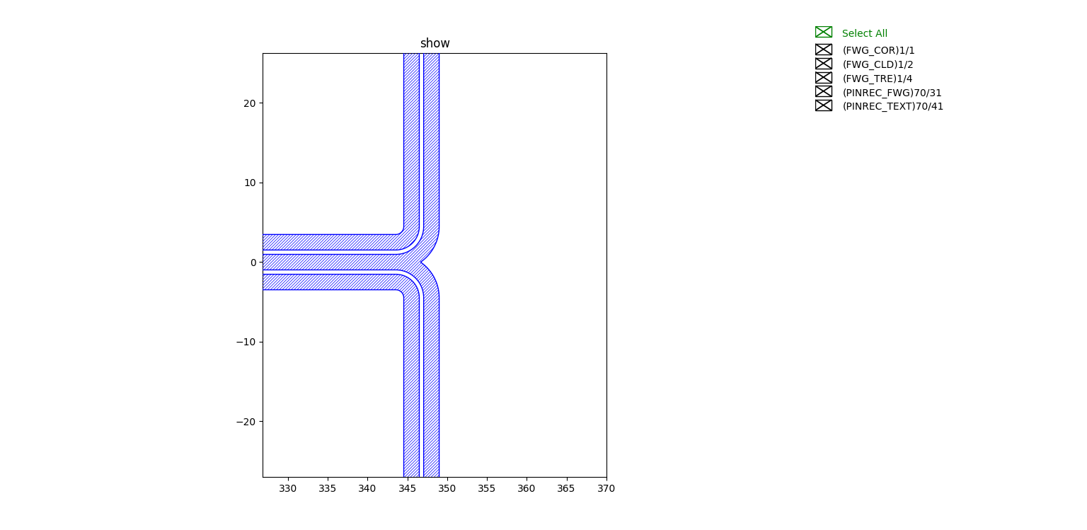
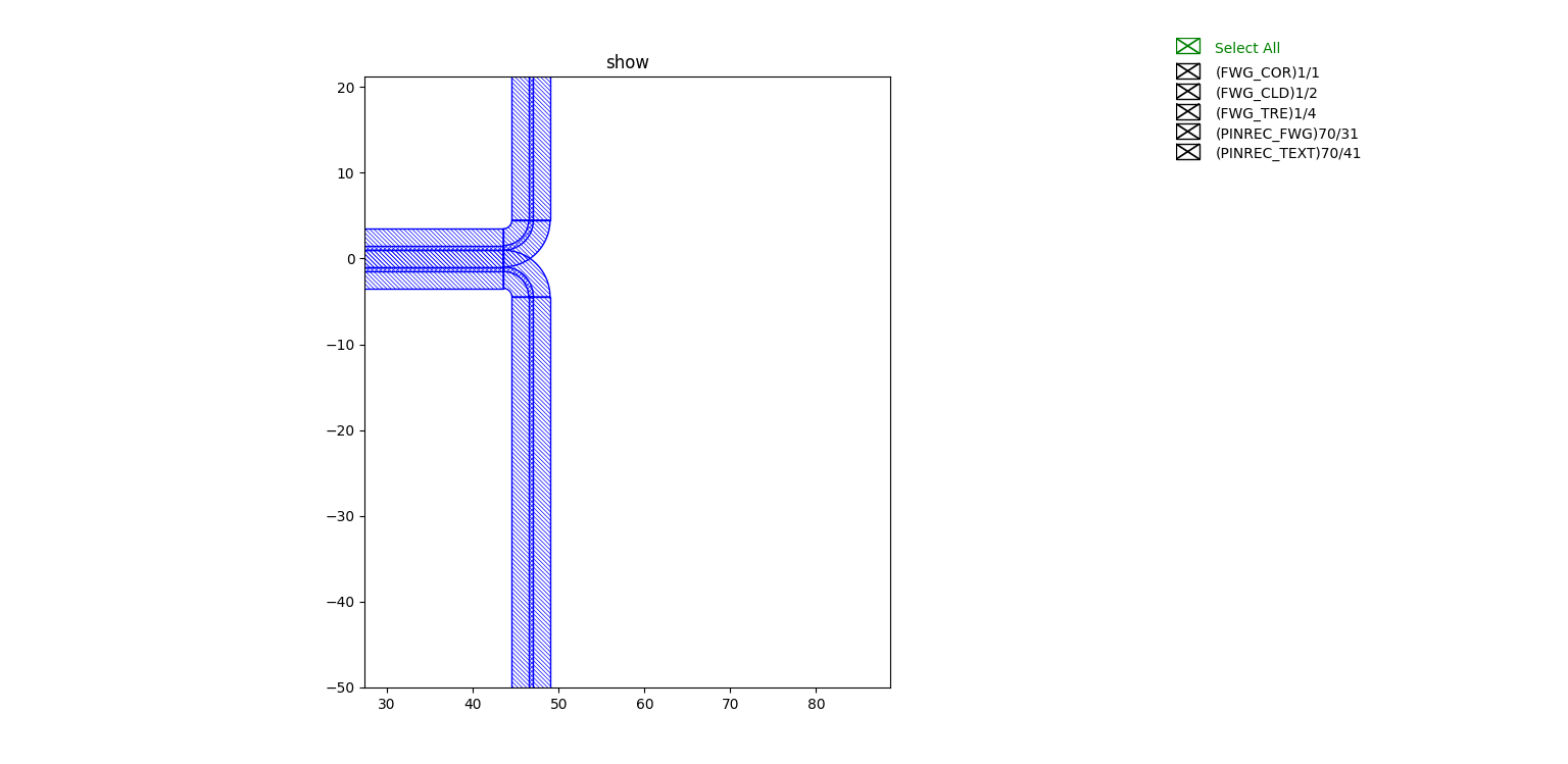
The left-hand side is the layout containing all the layer information, partially enlarged as follows
The right-hand side is obtained by Boolean operations