Link Electrical pad with turning angle
Full script
from fnpcell import all as fp
from gpdk import all as pdk
from gpdk.technology import get_technology

@dataclass(frozen=True)
class CircularBendFactory:
    radius: float = 80
    def __call__(self, central_angle: float):
        bend = fp.g.CircularBend(radius=self.radius, radians=central_angle)
        return bend, self.radius

@fp.pcell_class()

class LinkedElec2(fp.PCell):
    # fmt: off

    def build(self):
        insts, elems, ports = super().build()
        TECH = get_technology()
        pad_w = pdk.BondPad(pad_width=120, pad_height=60)
        pad = pdk.BondPad(pad_width=60, pad_height=60)
        start_pads_0 = [
            pad_w.translated(-110, -30),
            pad_w.translated(20, -30),
            pad_w.translated(260, -30),
            pad.translated(560, -30),
            pad_w.translated(660, -30),
            pad.translated(760, -30),
            pad.translated(830, -30),
            pad.translated(900, -30),
            pad.translated(970, -30),
        ]
        start_pads_1 = [
            pad.translated(-70, 120),
            pad.translated(60, 120),
            pad_w.translated(170, 120),
            pad_w.translated(360, 120),
            pad_w.translated(490, 120),
            pad.translated(600, 120),
            pad.translated(720, 120),
            pad.translated(780, 120),
            pad.translated(850, 120),
            pad.translated(920, 120),
            pad.translated(990, 120),
        ]

        end_pads_c0 = [
            # center
            pad_w.translated(1220, 1200),
            pad_w.translated(1680, 1200),
        ]

        end_pads_t0 = [
            # top
            pad.translated(2200, 2210),
            pad.translated(2200, 2140),
            pad.translated(2200, 2070),
            pad.translated(2200, 2000),
        ]

        end_pads_b0 = [
            # bottom
            pad_w.rotated(degrees=90).translated(2340, 840),
            pad_w.rotated(degrees=90).translated(2200, 740),
            pad.translated(2270, 645),
            pad.translated(2200, 610),
            pad.translated(2270, 575),
            pad.translated(2200, 540),
            pad.translated(2270, 505),
            pad.translated(2340, 470),
            pad.translated(2410, 435),
            pad.translated(2480, 400),
            pad.translated(2270, 365),
            pad.translated(2340, 330),
            pad.translated(2410, 295),
            pad.translated(2480, 260),

        ]

        to = fp.Waypoint
        MT = "ep_0"
        M2_20 = TECH.METAL.M2.W20
        MT_20 = TECH.METAL.MT.W20
        M2_40 = TECH.METAL.M2.W40
        MT_40 = TECH.METAL.MT.W40
        M2_80 = TECH.METAL.M2.W80
        MT_80 = TECH.METAL.MT.W80

        # fitting_function_80 = None
        # fitting_function_20 = None
        fitting_function_80 = TECH.FITTING_FUNCTION.Stubbed(stub_width=80, stub_right_angle=False)
        fitting_function_20 = TECH.FITTING_FUNCTION.Stubbed(stub_width=20, stub_right_angle=False)
        # fitting_function_80 = TECH.FITTING_FUNCTION.Stubbed(stub_width=80, stub_right_angle=True)
        # fitting_function_20 = TECH.FITTING_FUNCTION.Stubbed(stub_width=20, stub_right_angle=True)
        # fitting_function_80 = TECH.FITTING_FUNCTION.SmoothCircular(radius=80)
        # fitting_function_20 = TECH.FITTING_FUNCTION.SmoothCircular(radius=20)
        device = fp.Linked(
            metal_min_distance=150,
            metal_start_distance=150,
            metal_end_distance=150,
            metal_fitting_function=fitting_function_80,
            links=[
                # top
                fp.LinkBetween(
                    start_pads_0[0][MT].with_orientation(degrees=90), end_pads_t0[0][MT].with_orientation(degrees=180),
                    # waypoints=[to(400, 1840, 0), to(500, 1940, 90)],
                    waypoints=[fp.Offset.until_y(1840), fp.Offset.until_x(500)],
                    min_distance=40,
                    metal_line_type=[(0, M2_40), (300, MT_40)],
                ),
                fp.LinkBetween(
                    start_pads_1[0][MT].with_orientation(degrees=90), end_pads_t0[1][MT].with_orientation(degrees=180),
                    waypoints=[to(500, 1780, 0), to(600, 1880, 90)],
                    min_distance=20,
                    metal_line_type=[(0, MT_20)],
                ),
                fp.LinkBetween(
                    start_pads_0[1][MT].with_orientation(degrees=90), end_pads_t0[2][MT].with_orientation(degrees=180),
                    waypoints=[to(600, 1720, 0), to(700, 1820, 90)],
                    min_distance=20,
                    metal_line_type=[(0, M2_40), (300, MT_40)],
                ),
                fp.LinkBetween(
                    start_pads_1[1][MT].with_orientation(degrees=90), end_pads_t0[3][MT].with_orientation(degrees=180),
                    waypoints=[to(700, 1680, 0), to(800, 1780, 90) ],
                    min_distance=20,
                    metal_line_type=[(0, MT_20)],
                ),
                # center
                fp.LinkBetween(
                    start_pads_1[2][MT].with_orientation(degrees=90), end_pads_c0[0][MT].with_orientation(degrees=180),
                    metal_line_type=[(0, MT_80)],
                ),
                fp.LinkBetween(
                    start_pads_0[2][MT].with_orientation(degrees=90), end_pads_c0[1][MT].with_orientation(degrees=-90),
                    start_distance=1140,
                    metal_line_type=[(0, M2_80), (300, MT_80)],
                ),
                # bottom
                fp.LinkBetween(
                    start_pads_1[3][MT].with_orientation(degrees=90), end_pads_b0[0][MT].with_orientation(degrees=90),
                    metal_line_type=[(0, MT_80), (-200, M2_80)],
                ),
                fp.LinkBetween(
                    start_pads_1[4][MT].with_orientation(degrees=90), end_pads_b0[1][MT].with_orientation(degrees=90),
                    metal_line_type=[(0, MT_80)],
                ),
                fp.LinkBetween(
                    start_pads_0[3][MT].with_orientation(degrees=90), end_pads_b0[2][MT].with_orientation(degrees=180),
                    metal_line_type=[(0, M2_40), (300, MT_40), (-200, M2_40)],
                ),
                fp.LinkBetween(
                    start_pads_1[5][MT].with_orientation(degrees=90), end_pads_b0[3][MT].with_orientation(degrees=180),
                    metal_line_type=[(0, MT_20)],
                ),
                fp.LinkBetween(
                    start_pads_0[4][MT].with_orientation(degrees=90), end_pads_b0[4][MT].with_orientation(degrees=180),
                    metal_line_type=[(0, M2_40), (300, MT_40), (-200, M2_40)],
                ),
                #
                fp.LinkBetween(
                    start_pads_1[6][MT].with_orientation(degrees=90), end_pads_b0[5][MT].with_orientation(degrees=180),
                    metal_line_type=[(-240, M2_20)],
                ),
                fp.LinkBetween(
                    start_pads_1[7][MT].with_orientation(degrees=90), end_pads_b0[6][MT].with_orientation(degrees=180),
                    # start_distance=90,
                    metal_line_type=[(-200, M2_20)],
                ),
                fp.LinkBetween(
                    start_pads_1[8][MT].with_orientation(degrees=90), end_pads_b0[7][MT].with_orientation(degrees=180),
                    # start_distance=60,
                    metal_line_type=[(-200, M2_20)],
                ),
                fp.LinkBetween(
                    start_pads_1[9][MT].with_orientation(degrees=90), end_pads_b0[8][MT].with_orientation(degrees=180),
                    # start_distance=30,
                    metal_line_type=[(-200, M2_20)],
                ),
                fp.LinkBetween(
                    start_pads_1[10][MT].with_orientation(degrees=90), end_pads_b0[9][MT].with_orientation(degrees=180),
                    metal_line_type=[(-270, M2_20)],
                ),
                #
                fp.LinkBetween(
                    start_pads_0[5][MT].with_orientation(degrees=90), end_pads_b0[10][MT].with_orientation(degrees=-90),
                    start_distance=90,
                    metal_line_type=[(0, M2_20)],
                    fitting_function=fitting_function_20,
                ),
                fp.LinkBetween(
                    start_pads_0[6][MT].with_orientation(degrees=90), end_pads_b0[11][MT].with_orientation(degrees=-90),
                    start_distance=60,
                    metal_line_type=[(0, M2_20)],
                    fitting_function=fitting_function_20,
                ),
                fp.LinkBetween(
                    start_pads_0[7][MT].with_orientation(degrees=90), end_pads_b0[12][MT].with_orientation(degrees=-90),
                    start_distance=30,
                    metal_line_type=[(0, M2_20)],
                    fitting_function=fitting_function_20,
                ),
                fp.LinkBetween(
                    start_pads_0[8][MT].with_orientation(degrees=0), end_pads_b0[13][MT].with_orientation(degrees=-90),
                    start_distance=0,
                    metal_line_type=[(0, M2_20)],
                    fitting_function=fitting_function_20,
                ),
            ],
            ports=[] #[sb10["op_0"], s40["op_1"]],
        )
        insts += device
        # fmt: on
        return insts, elems, ports

if __name__ == "__main__":
    from pathlib import Path
    import gpdk.components.all
    gds_file = Path(__file__).parent / "local" / Path(__file__).with_suffix(".gds").name
    library = fp.Library()
    TECH = get_technology()
    # =============================================================
    # fmt: off
    library += LinkedElec2()
    # fmt: on
    # =============================================================
    fp.export_gds(library, file=gds_file)
    fp.export_pls(library, file=gds_file.with_suffix(".pls"), components=gpdk.components.all)
    fp.plot(library)
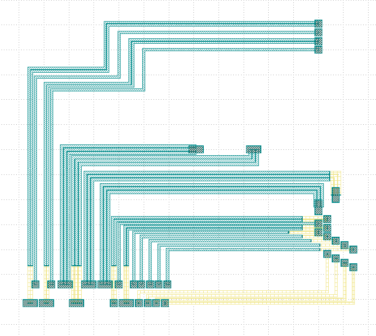
Run the full program once to generate the following GDS layout:
Parameters and testing description
Components positioning
There are a large number of BondPads in the entire layout, but they all consist of two sizes of Bond Pads: pad_w and pad.
pad_w = pdk.BondPad(pad_width=120, pad_height=60)
pad = pdk.BondPad(pad_width=60, pad_height=60)
The following calls to pad_w and pad are made multiple times to generate the BondPad group, and the following comments within the code explain what each part does.
# Create the first set of starting pads
start_pads_0 = [
    pad_w.translated(-110, -30),
    pad_w.translated(20, -30),
    pad_w.translated(260, -30),
    pad.translated(560, -30),
    pad_w.translated(660, -30),
    pad.translated(760, -30),
    pad.translated(830, -30),
    pad.translated(900, -30),
    pad.translated(970, -30),
]
# Create the second set of starting pads
start_pads_1 = [
    pad.translated(-70, 120),
    pad.translated(60, 120),
    pad_w.translated(170, 120),
    pad_w.translated(360, 120),
    pad_w.translated(490, 120),
    pad.translated(600, 120),
    pad.translated(720, 120),
    pad.translated(780, 120),
    pad.translated(850, 120),
    pad.translated(920, 120),
    pad.translated(990, 120),
]
# Create pads for the middle part of the layout
end_pads_c0 = [
    # center
    pad_w.translated(1220, 1200),
    pad_w.translated(1680, 1200),
]
# Create pads for the top part of the layout
end_pads_t0 = [
    # top
    pad.translated(2200, 2210),
    pad.translated(2200, 2140),
    pad.translated(2200, 2070),
    pad.translated(2200, 2000),
]
# Create pads for the bottom part of the layout
end_pads_b0 = [
    # bottom
    pad_w.rotated(degrees=90).translated(2340, 840),
    pad_w.rotated(degrees=90).translated(2200, 740),
    pad.translated(2270, 645),
    pad.translated(2200, 610),
    pad.translated(2270, 575),
    pad.translated(2200, 540),
    pad.translated(2270, 505),
    pad.translated(2340, 470),
    pad.translated(2410, 435),
    pad.translated(2480, 400),
    pad.translated(2270, 365),
    pad.translated(2340, 330),
    pad.translated(2410, 295),
    pad.translated(2480, 260),
]
# Instantiate the waypoint function as to for easy calling
to = fp.Waypoint
# Use MT instead of "ep_0" to facilitate the use of the connection later
MT = "ep_0"
# Call different types and widths of line types for later use when setting metal_line_type
M2_20 = TECH.METAL.M2.W20
MT_20 = TECH.METAL.MT.W20
M2_40 = TECH.METAL.M2.W40
MT_40 = TECH.METAL.MT.W40
M2_80 = TECH.METAL.M2.W80
MT_80 = TECH.METAL.MT.W80
The code below controls the corner of the wiring: if None, the corner is right angle by default. If TECH.FITTING_FUNCTION.Stubbed, the corner is a 45° angle of the specified length. If set the code to TECH.FITTING_FUNCTION.SmoothCircular, the corner becomes a rounded corner with the specified radius.
fitting_function_80 = None
fitting_function_20 = None
# fitting_function_80 = TECH.FITTING_FUNCTION.Stubbed(stub_width=80, stub_right_angle=False)
# fitting_function_20 = TECH.FITTING_FUNCTION.Stubbed(stub_width=20, stub_right_angle=False)
# fitting_function_80 = TECH.FITTING_FUNCTION.Stubbed(stub_width=80, stub_right_angle=True)
# fitting_function_20 = TECH.FITTING_FUNCTION.Stubbed(stub_width=20, stub_right_angle=True)
# fitting_function_80 = TECH.FITTING_FUNCTION.SmoothCircular(radius=40)
# fitting_function_20 = TECH.FITTING_FUNCTION.SmoothCircular(radius=20)
The default right angle is tested first and the following figure is obtained.
From the above figure, we can see that the corners are right angles, next comment out the None code, open the following two lines of code and run.
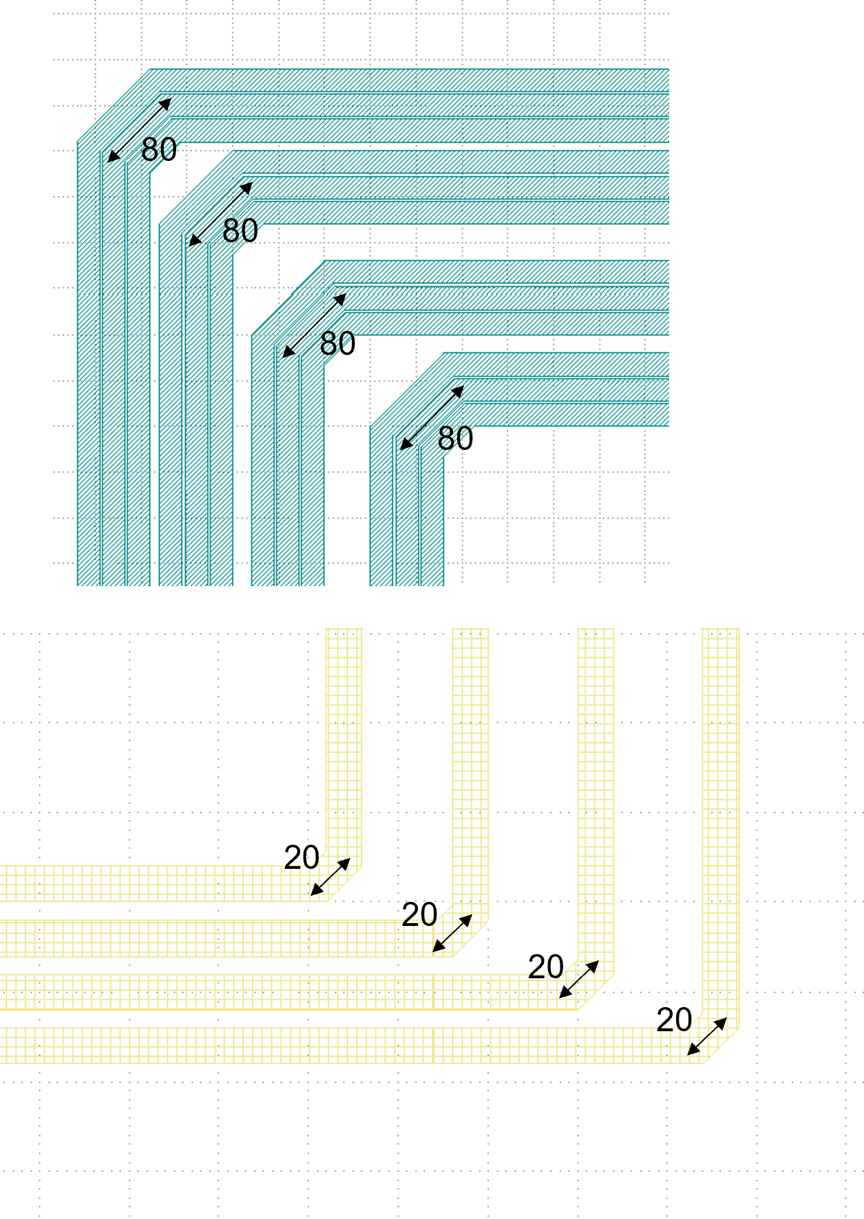
fitting_function_80 = TECH.FITTING_FUNCTION.Stubbed(stub_width=80, stub_right_angle=False)
fitting_function_20 = TECH.FITTING_FUNCTION.Stubbed(stub_width=20, stub_right_angle=False)
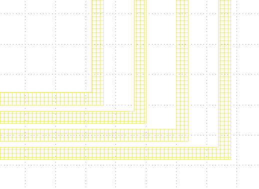
After running it, we can see that it is still a right angle and nothing has changed because stub_right_angle=False, we change it to True and run it once. From the figure below, we can see that the measured length at the center line of the corner are 80 and 20 as set.
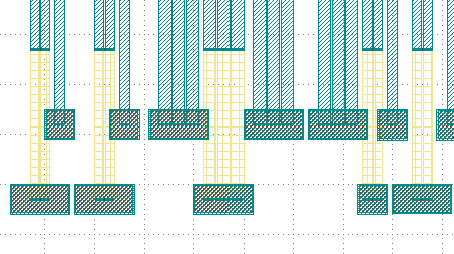
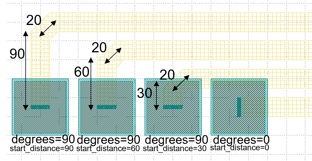
The code below mainly controls the connection of the four groups of pads at the bottom right of the layout, specifying the direction of the two end lines, the starting distance, the type of metal wire and the fitting function, etc. After running, the layout fragment is intercepted and marked with a description.
fp.LinkBetween(
    start_pads_0[5][MT].with_orientation(degrees=90), end_pads_b0[10][MT].with_orientation(degrees=-90),
    start_distance=90,
    metal_line_type=[(0, M2_20)],
    fitting_function=fitting_function_20,
),
fp.LinkBetween(
    start_pads_0[6][MT].with_orientation(degrees=90), end_pads_b0[11][MT].with_orientation(degrees=-90),
    start_distance=60,
    metal_line_type=[(0, M2_20)],
    fitting_function=fitting_function_20,
),
fp.LinkBetween(
    start_pads_0[7][MT].with_orientation(degrees=90), end_pads_b0[12][MT].with_orientation(degrees=-90),
    start_distance=30,
    metal_line_type=[(0, M2_20)],
    fitting_function=fitting_function_20,
),
fp.LinkBetween(
    start_pads_0[8][MT].with_orientation(degrees=0), end_pads_b0[13][MT].with_orientation(degrees=-90),
    start_distance=0,
    metal_line_type=[(0, M2_20)],
    fitting_function=fitting_function_20,
),
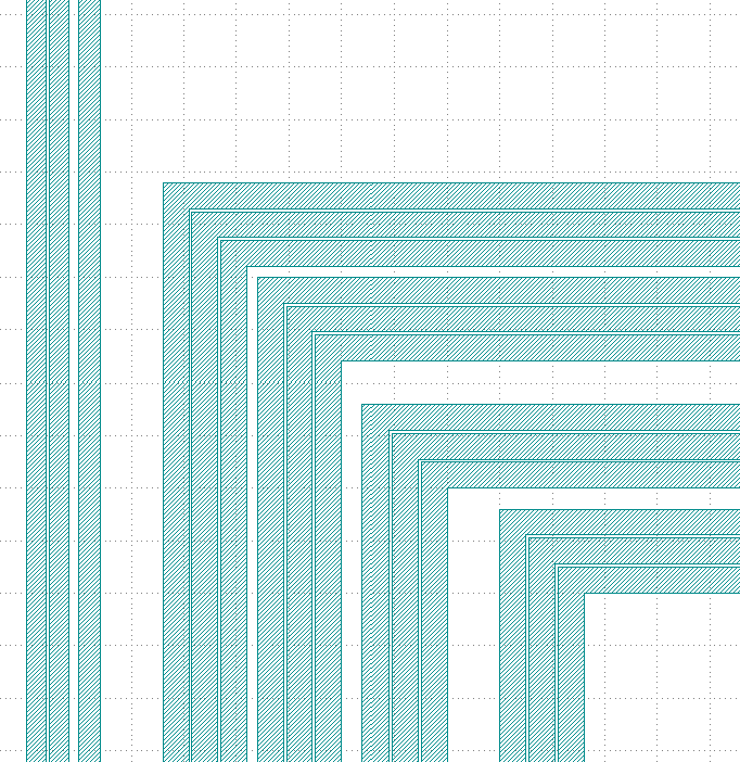
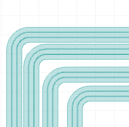
After the testing of the 45° corner is completed, we next test the rounded corners.
fitting_function_80 = TECH.FITTING_FUNCTION.SmoothCircular(radius=80)
fitting_function_20 = TECH.FITTING_FUNCTION.SmoothCircular(radius=20)
Since the radius value is not set properly, the error is reported after running.
We changed 80 to 40 and ran it again, and took the following part of the corners from the layout, from which we can see that the corners are changed from straight lines to smooth rounded shapes.
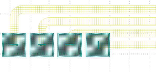
Finally, as shown in the following image segment, different line types appear in the same linked line. Refer to the relevant instructions in the (Link Electrical pad with turning angle) file for details on how to use it.