Simplify layout by fp.use_sketch_view
In this section, we will introduce the function fp.use_sketch_view to help users become more efficiently when designing layouts. In a complicate photonic circuit, often building up with tens or hundreds of components, it is easy to face the situation that we need huge amount of time to generate GDS file but only want to see a small part of change in the circuit. The real case is that when implementing the waypoints or waylines between two components, we don’t even care about what the components really looks like but focus on the connection between the ports.
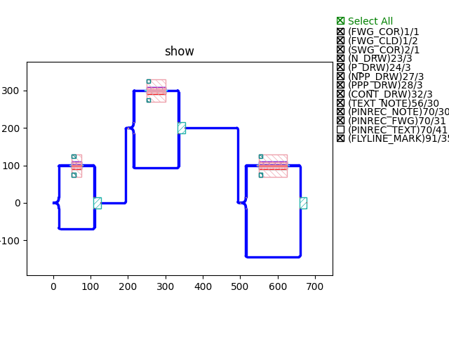
The function fp.use_sketch_view captures the geometry of every layer of the cell and simplify them into one single layer. During the first time of generating GDS file opening fp.use_sketch_view, PhotoCAD will automatically generate a sketch-view GDS file and JSon file indicating ports and layers information of the cell. After that, the formation of the GDS file of the circuit will based on the sketch-view GDS file and the non-sketch view cells.
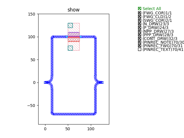
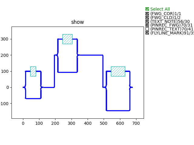
Here is an example of using fp.use_sketch_view in a MZM circuit, containing three MZIs with pn phase shifter on the top arm. The three MZIs are totally different and are all GDS imported cell.
mzm_l_200_pn_25 (length difference between two arms: 200 um, pn junction of the phase shifter: 25um)
y_splitter_taper_1
y_combiner_taper_1
phaseshifter_pn25
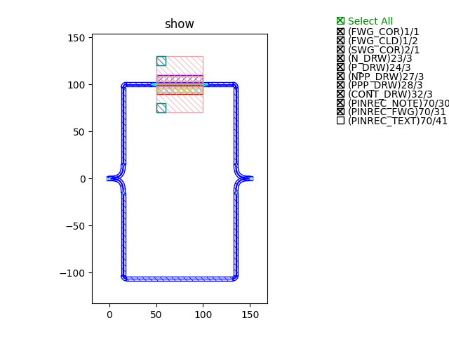
mzm_l_300_pn_50 (length difference between two arms: 300 um, pn junction of the phase shifter: 50um)
y_splitter_taper_5
y_combiner_taper_5
phaseshifter_pn50
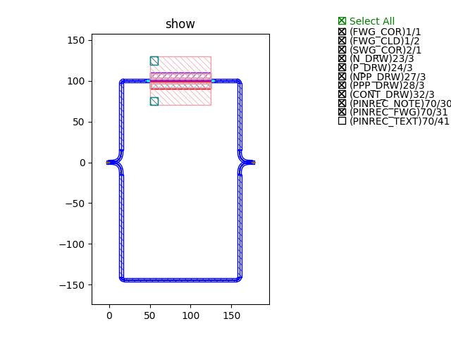
mzm_l_400_pn_75 (length difference between two arms: 400 um, pn junction of the phase shifter: 75um)
y_splitter_taper_10
y_combiner_taper_10
phaseshifter_pn75
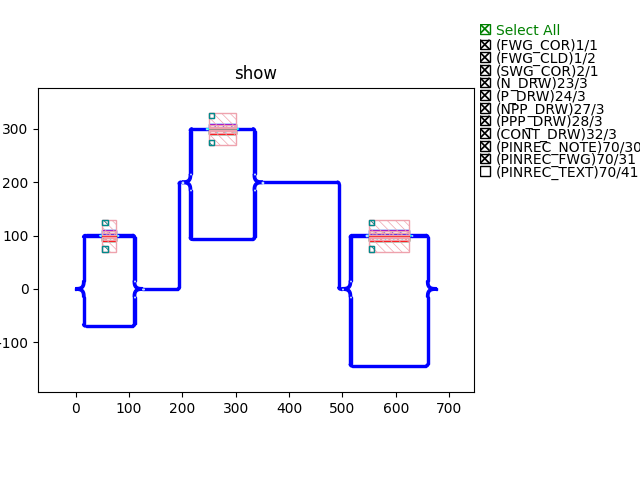
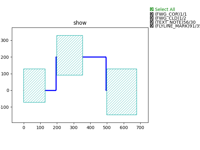
Connect three MZIs
Implement fp.use_sketch_view
fp.use_sketch_view(
        cell_to_be_sketched,
        conf = {
                    sketch_layer, # layer to be assigned to the sketched cell
                    marker_layer, # layer to be assigned to the marker(arrow) layer
                    marker_width, # width of the arrow
                    marker_length, # length of the arrow
                    silhouette_mode, # Boolean parameter. Default to be False, if True, the sketched cell will generate a boundary indicating the look of the true cell

                }
        )
The configuration parameter sets the sketched cell to the designated layer. The example code above will assign the sketched cell to TEXT_NOTE layer, and by the marker_layer will show the direction of the ports with an arrow.
sketch_layer
marker_layer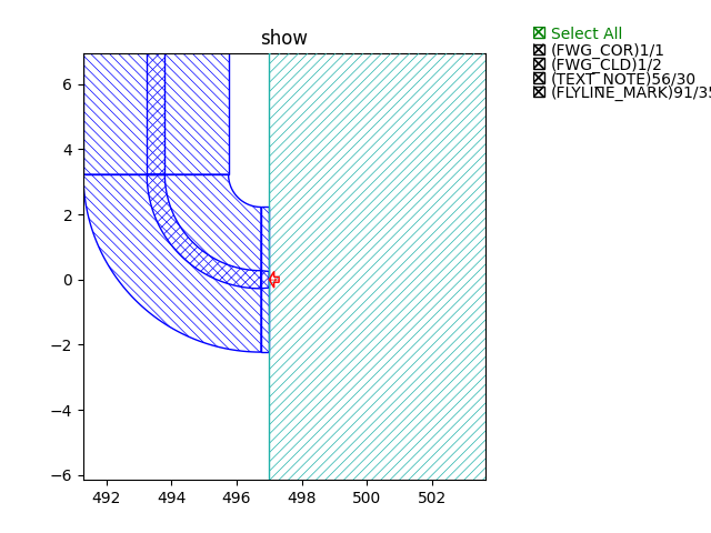
silhouette_mode=False(default)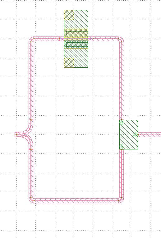
silhouette_mode=True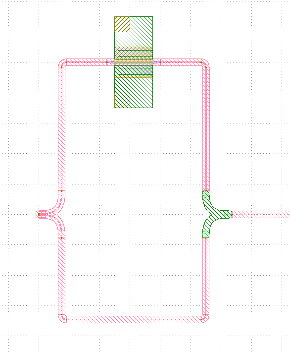
fp.use_sketch_view(mzm_l_200_pn_25, conf=conf)The first parameter of
fp.use_sketch_viewreads the cell which will be sketched. It could be any level of the circuit.
Note
The fp.use_sketch_view function has to be assign before adding circuit to library, e.g. library += Circuit(). Otherwise the setting will not change when exporting GDS file fp.export_gds.
gds_file = local_output_file(__file__).with_suffix(".gds") # assign the directory for exporting GDS file
library = fp.Library() # generate library for adding PCells, circuits

TECH = get_technology() # call PDK technology setting
conf = fp.SketchConf(sketch_layer=TECH.LAYER.TEXT_NOTE, marker_layer=TECH.LAYER.FLYLINE_MARK) # Set sketch view layers
fp.use_sketch_view(PnPhaseShifter, conf=conf) # Load sketch view function

library += mzm_l_400_pn_75() # Add PCells or circuits to library

fp.export_gds(library, file=gds_file) # Export contents in library to GDS file
Different usage of fp.use_sketch_view
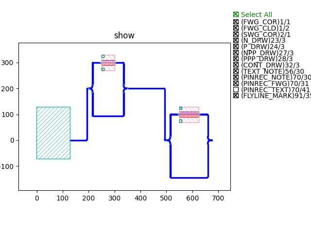
Sketch all MZMs
fp.use_sketch_view(mzm_l_200_pn_25, conf=conf)
fp.use_sketch_view(mzm_l_300_pn_50, conf=conf)
fp.use_sketch_view(mzm_l_400_pn_75, conf=conf)
Sketch all Phase Shifters
fp.use_sketch_view(phaseshifter_pn25, conf=conf)
fp.use_sketch_view(phaseshifter_pn50, conf=conf)
fp.use_sketch_view(phaseshifter_pn75, conf=conf)
Sketch all Combiners
fp.use_sketch_view(y_combiner_taper1, conf=conf)
fp.use_sketch_view(y_combiner_taper5, conf=conf)
fp.use_sketch_view(y_combiner_taper10, conf=conf)
Sketch only the first MZM
fp.use_sketch_view(mzm_l_200_pn_25, conf=conf)
GDS file build-time results
We track the build-up time of the GDS file when implementing different scenarios.
Circuit without any sketch view: 0.1482s
1st time open all MZMs sketch view: 0.1423s
2nd time open all MZMs sketch view: 0.0654s
Close all sketch view: 0.1529s
3rd time open all MZMs sketch view: 0.0659s
1st time open child cell (all phase shifters) sketch view: 0.1594s
2nd time open child cell (all phase shifters) sketch view: 0.1385s
Close all child cell sketch view: 0.1483s
From the above results we can see that fp.use_sketch_view increases two to three times the speed of generating the GDS file. First time opening the sketch view needs some time to generate the GDS and Json files of the sketched cell, but after that the build-up time can be efficiently saved.
Example Scripts
Here we only show the script of the top circuit of the above example.
class Topcircuit(fp.PCell, locked=True):
    def build(self) -> Tuple[fp.InstanceSet, fp.ElementSet, fp.PortSet]:
        insts, elems, ports = super().build()
        TECH = get_technology()

        mzm1 = mzm_l_200_pn_25() # Call and place the three child mzms
        mzm2 = mzm_l_300_pn_50().translated(200, 200)
        mzm3 = mzm_l_400_pn_75().translated(500, 0)

        link = fp.create_links( # Link the three child mzms
            link_type=TECH.WG.FWG.C.WIRE,
            bend_factory=TECH.WG.FWG.C.WIRE.BEND_CIRCULAR,
            specs=[
                fp.LinkBetween(
                    end=mzm2["op_0"],
                    start=mzm1["op_1"]
                ),
                fp.LinkBetween(
                    start=mzm2["op_1"],
                    end=mzm3["op_0"]
                ),

            ]
        )

        insts += mzm1
        insts += mzm2
        insts += mzm3
        insts += link

        return insts, elems, ports


if __name__ == "__main__":
    import sys
    from time import perf_counter
    from gpdk.util.path import local_output_file

    gds_file = local_output_file(__file__).with_suffix(".gds")
    library = fp.Library()

    TECH = get_technology()
    conf = fp.SketchConf(sketch_layer=TECH.LAYER.TEXT_NOTE, marker_layer=TECH.LAYER.FLYLINE_MARK)

    def test_build(tag: str): # Create a build test function to count the time to build up GDS file in different situations.
        start_time = perf_counter()
        library = fp.Library()
        library += Topcircuit()
        fp.export_gds(library, file=gds_file.with_suffix(f".{tag}.gds"))
        print(f"{tag} view elapsed time: {perf_counter()-start_time:.4f}\n")

    tag = sys.argv[1] if len(sys.argv) == 2 else "test"
    if tag.startswith("original"):
        test_build(tag)
    elif tag.startswith("mzm"):
        fp.use_sketch_view(mzm_l_200_pn_25, conf=conf) # Assign fp.use_sketch_view function before test_build function
        fp.use_sketch_view(mzm_l_300_pn_50, conf=conf)
        fp.use_sketch_view(mzm_l_400_pn_75, conf=conf)
        test_build(tag)
    elif tag.startswith("ps"):
        fp.use_sketch_view(phaseshifter_pn25, conf=conf) # Assign fp.use_sketch_view function before test_build function
        fp.use_sketch_view(phaseshifter_pn50, conf=conf)
        fp.use_sketch_view(phaseshifter_pn75, conf=conf)
        test_build(tag)
    elif tag.startswith("combiner"):
        fp.use_sketch_view(y_combiner_taper1, conf=conf) # Assign fp.use_sketch_view function before test_build function
        fp.use_sketch_view(y_combiner_taper5, conf=conf)
        fp.use_sketch_view(y_combiner_taper10, conf=conf)
        test_build(tag)
    elif tag.startswith("test"):


        import os
        import subprocess

        # Test 1 : close sketch view
        subprocess.run([sys.executable, sys.argv[0], "original1"], env=os.environ)
        # Test 2 : open sketch view 1
        subprocess.run([sys.executable, sys.argv[0], "mzml"], env=os.environ)
        # Test 3 : open sketch view 2
        subprocess.run([sys.executable, sys.argv[0], "mzm2"], env=os.environ)
        # Test 4 : close sketch view
        subprocess.run([sys .executable, sys.argv[0],"original2"], env=os.environ )
        # Test 5 : open sketch view 3
        subprocess.run([sys.executable, sys.argv[0],"mzm3"], env=os.environ)
        # Test 6 : open child cell sketch 1 view
        subprocess.run([sys.executable, sys.argv[0], "ps1"], env=os.environ)
        # Test 7 : open child cell sketch 2 view:
        subprocess.run([sys.executable, sys.argv[0], "ps2"], env=os.environ)
        # Test 8 : close child cell sketch view
        subprocess.run([sys.executable, sys.argv[0], "original3"], env=os.environ)
        # Test 9 : open sketch view phase shifter 3
        subprocess.run([sys.executable, sys.argv[0],"ps3"], env=os.environ)
        # Test 9 : open sketch view combiner
        subprocess.run([sys.executable, sys.argv[0],"combiner"], env=os.environ)