步骤3: 利用基本链路搭建复杂链路
在步骤2(步骤2: 利用基础模块搭建基本链路)中已经利用基础模块搭建了基本的链路。这一小节,继续通过这些基本链路的连接搭建复杂链路实现更多的功能,例如马曾结构。基本模块之间的连接,主要提供三种方式:
下面将从这三种连接类型出发,分别利用这三种方式搭建马曾结构链路。
U型定长
导入步骤2(步骤2: 利用基础模块搭建基本链路)创建的定向耦合器:
from step.step2.directional_coupler_bend import DirectionalCouplerBend
定义马曾干涉仪类,方便后面直接调用:
class MZI(fp.PCell):

    def build(self):
        insts, elems, ports = super().build()
        TECH = get_technology()

        dc = DirectionalCouplerBend(
            coupler_spacing=0.5,
            coupler_length=6,
            bend_radius=10,
            straight_after_bend=6,
            waveguide_type=TECH.WG.FWG.C.WIRE
        )
        dc1 = dc.translated(-100, 0)
        insts += dc1
        dc2 = dc.translated(100, 0)
        insts += dc2

        device = fp.create_links(
            link_type=TECH.WG.FWG.C.EXPANDED,
            bend_factory=TECH.WG.FWG.C.WIRE.BEND_CIRCULAR,
            specs=[
                fp.LinkBetween(
                    dc1["op_2"],
                    dc2["op_1"],
                    target_length=500,
                ),
                fp.LinkBetween(
                    dc1["op_3"],
                    dc2["op_0"],
                    target_length=320,
                ),
            ],
        )
        insts += device

        ports += dc1["op_0"].with_name("in1")
        ports += dc1["op_1"].with_name("in2")
        ports += dc2["op_2"].with_name("out1")
        ports += dc2["op_3"].with_name("out2")

        # fmt: on
        return insts, elems, ports
其中:
device = fp.create_links(
    link_type=TECH.WG.FWG.C.EXPANDED,
    bend_factory=TECH.WG.FWG.C.WIRE.BEND_CIRCULAR,
    specs=[
        fp.LinkBetween(
            dc1["op_2"],
            dc2["op_1"],
            target_length=500,
        ),
        fp.LinkBetween(
            dc1["op_3"],
            dc2["op_0"],
            target_length=320,
        ),
    ],
)
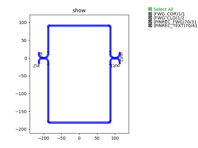
通过"target_length=320"来实现U型定长连接的。
最终,通过调用类实现生成版图并展示图例:
device += MZI()
fp.export_gds(device, file=gds_file)
fp.plot(device)
采用U型定长方式连接的马曾结构图例展示
路径点
导入步骤2(步骤2: 利用基础模块搭建基本链路)创建的定向耦合器:
from step.step2.directional_coupler_bend import DirectionalCouplerBend
定义马曾干涉仪类,方便后面直接调用:
class MZI(fp.PCell):
    def build(self):
        insts, elems, ports = super().build()
        TECH = get_technology()

        dc = DirectionalCouplerBend(
            coupler_spacing=0.5,
            coupler_length=6,
            bend_radius=10,
            straight_after_bend=6,
            waveguide_type=TECH.WG.FWG.C.WIRE
        )
        dc1 = dc.translated(-100, 0)
        insts += dc1
        dc2 = dc.translated(100, 0)
        insts += dc2

        device = fp.create_links(
            link_type=TECH.WG.FWG.C.EXPANDED,
            bend_factory=TECH.WG.FWG.C.WIRE.BEND_CIRCULAR,
            specs=[
                fp.LinkBetween(
                    dc1["op_2"],
                    dc2["op_1"],
                    waypoints=[
                        fp.Waypoint(-50, -70, -90),
                        fp.Waypoint(0, -100, 0),
                        fp.Waypoint(50, -70, 90),
                    ]
                ),
                fp.LinkBetween(
                    dc1["op_3"],
                    dc2["op_0"],
                    waypoints=[
                        fp.Waypoint(-50, 70, 90),
                        fp.Waypoint(0, 100, 0),
                        fp.Waypoint(50, 70, -90),
                    ]
                ),
            ],
        )
        insts += device

        ports += dc1["op_0"].with_name("in1")
        ports += dc1["op_1"].with_name("in2")
        ports += dc2["op_2"].with_name("out1")
        ports += dc2["op_3"].with_name("out2")

        # fmt: on
        return insts, elems, ports
其中:
device = fp.create_links(
    link_type=TECH.WG.FWG.C.EXPANDED,
    bend_factory=TECH.WG.FWG.C.WIRE.BEND_CIRCULAR,
    specs=[
        fp.LinkBetween(
            dc1["op_2"],
            dc2["op_1"],
            waypoints=[
                fp.Waypoint(-50, -70, -90),
                fp.Waypoint(0, -100, 0),
                fp.Waypoint(50, -70, 90),
            ]
        ),
        fp.LinkBetween(
            dc1["op_3"],
            dc2["op_0"],
            waypoints=[
                fp.Waypoint(-50, 70, 90),
                fp.Waypoint(0, 100, 0),
                fp.Waypoint(50, 70, -90),
            ]
        ),
    ],
)
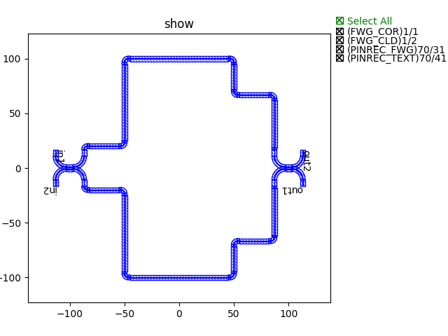
通过"waypoints"来实现路径点连接的,即连接路线通过所有设置的点。
最终,通过调用类实现生成版图并展示图例:
device += MZI()
fp.export_gds(device, file=gds_file)
fp.plot(device)
采用路径点方式连接的马曾结构图例展示
路径线
导入步骤2(步骤2: 利用基础模块搭建基本链路)创建的定向耦合器:
from step.step2.directional_coupler_bend import DirectionalCouplerBend
定义马曾干涉仪类,方便后面直接调用:
class MZI(fp.PCell):
def build(self):
insts, elems, ports = super().build()
TECH = get_technology()
dc = DirectionalCouplerBend(
coupler_spacing=0.5,
coupler_length=6,
bend_radius=10,
straight_after_bend=6,
waveguide_type=TECH.WG.FWG.C.WIRE
)
dc1 = dc.translated(-100, 0)
insts += dc1
dc2 = dc.translated(100, 0)
insts += dc2
device = fp.create_links(
link_type=TECH.WG.FWG.C.EXPANDED,
bend_factory=TECH.WG.FWG.C.WIRE.BEND_CIRCULAR,
specs=[
fp.LinkBetween(
dc1["op_2"],
dc2["op_1"],
waylines=[fp.until_y(-100)]
),
fp.LinkBetween(
dc1["op_3"],
dc2["op_0"],
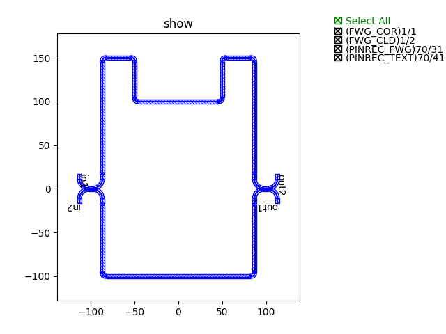
waylines=[fp.until_y(150),
fp.until_x(-50),
fp.until_y(100),
fp.until_x(50),
fp.until_y(150)]
),
],
)
insts += device
ports += dc1["op_0"].with_name("in1")
ports += dc1["op_1"].with_name("in2")
ports += dc2["op_2"].with_name("out1")
ports += dc2["op_3"].with_name("out2")
# fmt: on
return insts, elems, ports
其中:
device = fp.create_links(
    link_type=TECH.WG.FWG.C.EXPANDED,
    bend_factory=TECH.WG.FWG.C.WIRE.BEND_CIRCULAR,
    specs=[
        fp.LinkBetween(
            dc1["op_2"],
            dc2["op_1"],
            waylines=[fp.until_y(-100)]
        ),
        fp.LinkBetween(
            dc1["op_3"],
            dc2["op_0"],
            waylines=[fp.until_y(150),
                      fp.until_x(-50),
                      fp.until_y(100),
                      fp.until_x(50),
                      fp.until_y(150)]
        ),
    ],
)
通过"waylines"来实现路径线连接的。
最终,通过调用类实现生成版图并展示图例:
device += MZI()
fp.export_gds(device, file=gds_file)
fp.plot(device)
采用路径点方式连接的马曾结构图例展示