步骤2: 利用基础模块搭建基本链路
本案例利用基础模块实现了两个基本链路的搭建,包括:
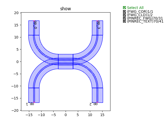
定向耦合器
导入步骤1(步骤1: 搭建链路基础模块)创建的基础模块,这里用到弯曲波导和直波导:
from step.step1.straight import Straight
from step.step1.bend_circular import BendCircular
定义定向耦合器类,方便后面直接调用:
class DirectionalCouplerBend(fp.PCell):

    coupler_spacing: float = fp.PositiveFloatParam(default=0.7, doc="Spacing between the two waveguide centre lines.")
    coupler_length: float = fp.PositiveFloatParam(default=6, doc="Length of the directional coupler")
    bend_radius: float = fp.PositiveFloatParam(required=False, doc="Bend radius for the auto-generated bends")
    straight_after_bend: float = fp.PositiveFloatParam(default=6, doc="Length of the straight waveguide after the bend")
    waveguide_type: CoreCladdingWaveguideType = fp.WaveguideTypeParam(type=CoreCladdingWaveguideType, doc="Waveguide parameters")
    port_names: fp.IPortOptions = fp.PortOptionsParam(count=4, default=["op_0", "op_1", "op_2", "op_3"])

    def _default_waveguide_type(self):
        return get_technology().WG.FWG.C.WIRE

    def build(self) -> Tuple[fp.InstanceSet, fp.ElementSet, fp.PortSet]:
        insts, elems, ports = super().build()
        # fmt: off
        coupler_spacing = self.coupler_spacing
        coupler_length = self.coupler_length
        bend_radius = self.bend_radius
        straight_after_bend = self.straight_after_bend
        waveguide_type = self.waveguide_type
        port_names = self.port_names

        if bend_radius is None:
            bend_radius = cast(float, waveguide_type.BEND_CIRCULAR.radius_eff)  # type: ignore

        dy = coupler_spacing / 2 + waveguide_type.core_width

        left_straight_after_bend = Straight(name="lafterbend", length=straight_after_bend, waveguide_type=waveguide_type)
        right_straight_after_bend = Straight(name="rafterbend",length=straight_after_bend, waveguide_type=waveguide_type)
        left_bend = BendCircular(name="lbend", degrees=90, radius=bend_radius, waveguide_type=waveguide_type)
        right_bend = BendCircular(name="rbend", degrees=90, radius=bend_radius, waveguide_type=waveguide_type)
        straight_coupler = Straight(name="coupler", length=coupler_length, anchor=fp.Anchor.CENTER, waveguide_type=waveguide_type, transform=fp.translate(0, -dy))

        bottom_half = fp.Connected(
            name="bottom",
            joints=[
                straight_coupler["op_0"] <= left_bend["op_0"],
                left_bend["op_1"] <= left_straight_after_bend["op_1"],
                #
                straight_coupler["op_1"] <= right_bend["op_1"],
                right_bend["op_0"] <= right_straight_after_bend["op_0"],
            ],
            ports=[
                left_straight_after_bend["op_0"],
                right_straight_after_bend["op_1"],
            ],
        )
        insts += bottom_half
        top_half = bottom_half.v_mirrored()
        insts += top_half
        ports += top_half["op_0"].with_name(port_names[0])
        ports += bottom_half["op_0"].with_name(port_names[1]),
        ports += bottom_half["op_1"].with_name(port_names[2]),
        ports += top_half["op_1"].with_name(port_names[3]),

        # fmt: on
        return insts, elems, ports
调用类,生成定向耦合器版图文件并显示图例:
library += DirectionalCouplerBend(name="f", coupler_spacing=0.5, coupler_length=6, bend_radius=10, straight_after_bend=6, waveguide_type=TECH.WG.FWG.C.WIRE)
fp.export_gds(library, file=gds_file)
fp.plot(library) += BendCircular(name="s", radius=15, waveguide_type=TECH.WG.FWG.C.WIRE)
fp.export_gds(library, file=gds_file)
fp.plot(library)
定向耦合器图例展示
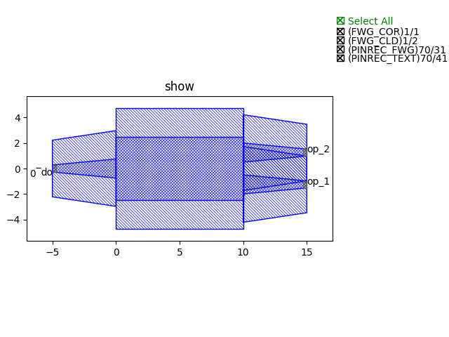
多模干涉仪
导入步骤1(步骤1: 搭建链路基础模块)创建的基础模块,这里用到直波导和过渡波导:
from step.step1.straight import Straight
from step.step1.taper_linear import TaperLinear
定义多模干涉仪类,方便后面直接调用:
class MMI1x2(fp.PCell):
    mid_wav_core_width: float = fp.PositiveFloatParam(default=5)
    wav_core_width: float = fp.PositiveFloatParam(default=1.5)
    length: float = fp.PositiveFloatParam(default=10)
    transition_length: float = fp.PositiveFloatParam(default=5)
    trace_spacing: float = fp.PositiveFloatParam(default=1)
    waveguide_type: CoreCladdingWaveguideType = fp.WaveguideTypeParam(type=CoreCladdingWaveguideType)

    def _default_waveguide_type(self):
        return get_technology().WG.FWG.C.WIRE

    def build(self) -> Tuple[fp.InstanceSet, fp.ElementSet, fp.PortSet]:
        insts, elems, ports = super().build()
        # fmt: off
        mid_wav_core_width = self.mid_wav_core_width
        wav_core_width=self.wav_core_width
        length = self.length
        transition_length = self.transition_length
        trace_spacing = self.trace_spacing
        waveguide_type = self.waveguide_type

        center_force_cladding_width = mid_wav_core_width+waveguide_type.cladding_width
        center_type = waveguide_type.updated(core_layout_width=mid_wav_core_width, cladding_layout_width=center_force_cladding_width)
        center = Straight(length=length, waveguide_type=center_type, anchor=fp.Anchor.START)
        insts += center

        wide_type = waveguide_type.updated(core_layout_width=wav_core_width, cladding_layout_width=waveguide_type.cladding_width + wav_core_width)
        narrow_type = waveguide_type
        taper_left = TaperLinear(length=transition_length, left_type=narrow_type, right_type=wide_type, anchor=fp.Anchor.END)
        taper_right = TaperLinear(length=transition_length, left_type=wide_type, right_type=narrow_type, anchor=fp.Anchor.START)


        taper_left_inst = taper_left.translated(0, 0)
        insts += taper_left_inst
        ports += taper_left_inst["op_0"].with_name("op_0")

        taper_right_inst1 = taper_right.translated(length, -(wav_core_width+trace_spacing)/2)
        insts += taper_right_inst1
        ports += taper_right_inst1["op_1"].with_name(f"op_1")
        taper_right_inst2 = taper_right.translated(length, (wav_core_width+trace_spacing)/2)
        insts += taper_right_inst2
        ports += taper_right_inst2["op_1"].with_name(f"op_2")

        # fmt: on
        return insts, elems, ports
调用类,生成MMI版图文件并显示图例:
library += MMI1x2()
fp.export_gds(library, file=gds_file)
fp.plot(library)
多模干涉仪图例展示